Cisco 6509 Installation Guide - Page 171
Removing and Installing a 4000 W DC-Input Power Supply
 |
UPC - 746320196077
View all Cisco 6509 manuals
Add to My Manuals
Save this manual to your list of manuals |
Page 171 highlights
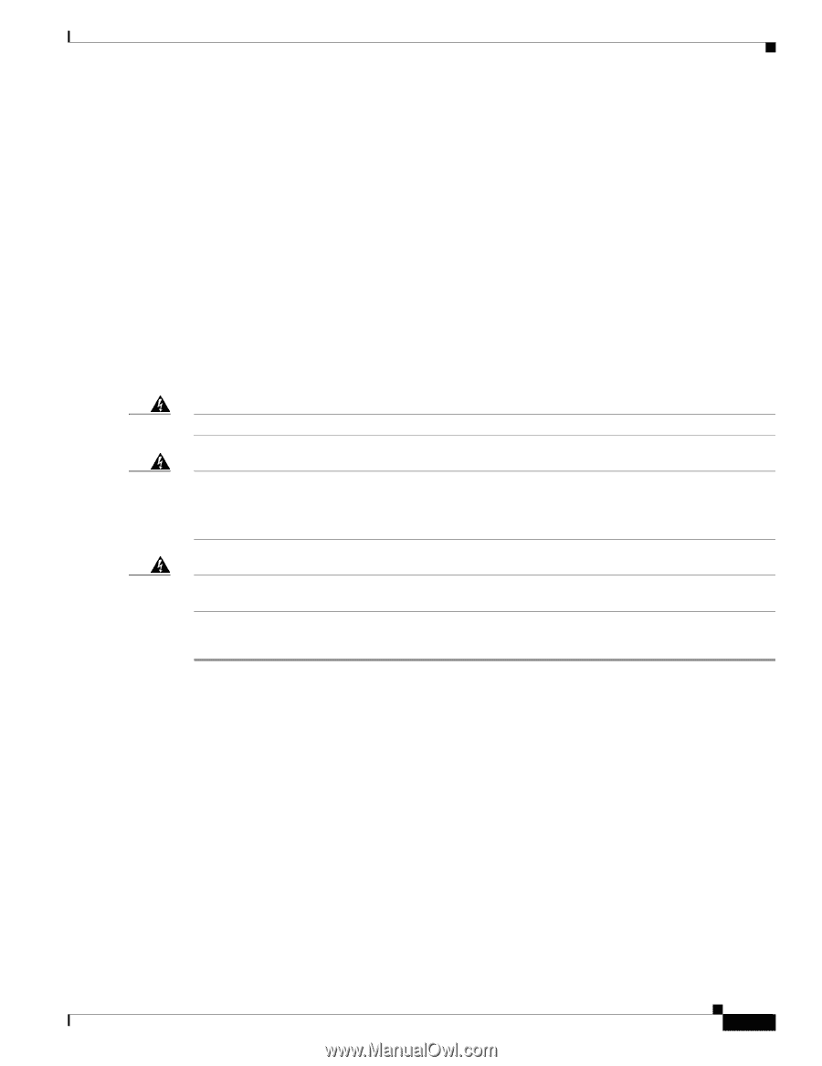
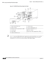
Chapter 4 Removal and Replacement Procedures Removing and Installing the DC-Input Power Supplies Removing and Installing a 4000 W DC-Input Power Supply This section covers the power supply removal and installation procedures for the 4000 W DC-input power supply and is divided into the following topics: • Required Tools, page 4-31 • Removing a 4000 W DC-Input Power Supply, page 4-31 • Installing a 4000 W DC-Input Power Supply, page 4-35 Required Tools Use a flat-blade or number 2 Phillips-head screwdriver to perform these procedures. Additionally, wire cutters may be necessary to cut cable tie-wraps. Removing a 4000 W DC-Input Power Supply Warning When installing the unit, always make the ground connection first and disconnect it last. Statement 42 Warning Before performing any of the following procedures, ensure that power is removed from the DC circuits. To ensure that all power is removed, locate the circuit breakers or fuses on the DC power lines that service the DC circuits. Turn OFF the DC power line circuit breakers and remove the DC power line fuses. Statement 322 Warning Voltage is present on the backplane when the system is operating. To reduce risk of an electric shock, keep hands and fingers out of the power supply bays and backplane areas. Statement 166 Follow these steps to remove a 4000 W DC-input power supply: Step 1 Step 2 Verify that power is off to the DC circuit connected to the DC-input power supply that you are removing. As an added precaution, place the appropriate safety flag and lockout devices at the source power circuit breaker, or place a piece of adhesive tape over the circuit breaker handle to prevent accidental power restoration while you are working on the circuit. Turn the power switch to the Off (0) position on the power supply that you are removing. (See Figure 4-24.) Turning off the power switch also disengages a pawl that unlocks the power supply from the chassis. OL-5781-04 Catalyst 6500 Series Switches Installation Guide 4-31
-
 1
1 -
2
-
3
-
4
-
5
-
6
-
7
-
8
-
9
-
10
-
11
-
12
-
13
-
14
-
15
-
16
-
17
-
18
-
19
-
20
-
21
-
22
-
23
-
24
-
25
-
26
-
27
-
28
-
29
-
30
-
31
-
32
-
33
-
34
-
35
-
36
-
37
-
38
-
39
-
40
-
41
-
42
-
43
-
44
-
45
-
46
-
47
-
48
-
49
-
50
-
51
-
52
-
53
-
54
-
55
-
56
-
57
-
58
-
59
-
60
-
61
-
62
-
63
-
64
-
65
-
66
-
67
-
68
-
69
-
70
-
71
-
72
-
73
-
74
-
75
-
76
-
77
-
78
-
79
-
80
-
81
-
82
-
83
-
84
-
85
-
86
-
87
-
88
-
89
-
90
-
91
-
92
-
93
-
94
-
95
-
96
-
97
-
98
-
99
-
100
-
101
-
102
-
103
-
104
-
105
-
106
-
107
-
108
-
109
-
110
-
111
-
112
-
113
-
114
-
115
-
116
-
117
-
118
-
119
-
120
-
121
-
122
-
123
-
124
-
125
-
126
-
127
-
128
-
129
-
130
-
131
-
132
-
133
-
134
-
135
-
136
-
137
-
138
-
139
-
140
-
141
-
142
-
143
-
144
-
145
-
146
-
147
-
148
-
149
-
150
-
151
-
152
-
153
-
154
-
155
-
156
-
157
-
158
-
159
-
160
-
161
-
162
-
163
-
164
-
165
-
 166
166 -
 167
167 -
 168
168 -
 169
169 -
 170
170 -
 171
171 -
 172
172 -
 173
173 -
 174
174 -
 175
175 -
 176
176 -
177
-
178
-
179
-
180
-
181
-
182
-
183
-
184
-
185
-
186
-
187
-
188
-
189
-
190
-
191
-
192
-
193
-
194
-
195
-
196
-
197
-
198
-
199
-
200
-
201
-
202
-
203
-
204
-
205
-
206
-
207
-
208
-
209
-
210
-
211
-
212
-
213
-
214
-
215
-
216
-
217
-
218
-
219
-
220
-
221
-
222
-
223
-
224
-
225
-
226
-
227
-
228
-
229
-
230
-
231
-
232
-
233
-
234
-
235
-
236
-
237
-
238
-
239
-
240
-
241
-
242
-
243
-
244
-
245
-
246
-
247
-
248
-
249
-
250
-
251
-
252
-
253
-
254
-
255
-
256
-
257
-
258
-
259
-
260
-
261
-
262
-
263
-
264
-
265
-
266
-
267
-
268
-
269
-
270
-
271
-
272
-
273
-
274
-
275
-
276
-
277
-
278
-
279
-
280
-
281
-
282
-
283
-
284
-
285
-
286
-
287
-
288
-
289
-
290
-
291
-
292
-
293
-
294
-
295
-
296
-
297
-
298
-
299
-
300
-
301
-
302
-
303
-
304
-
305
-
306
-
307
-
308
-
309
-
310
-
311
-
312
-
313
-
314
-
315
-
316
-
317
-
318
-
319
-
320
-
321
-
322
-
323
-
324
-
325
-
326
-
327
-
328
-
329
-
330
-
331
-
332
-
333
-
334
-
335
-
336
 |
 |