Cisco 6509 Installation Guide - Page 189
Step 5, Step 6, Step 7, Step 8, Step 9, Step 10, Step 11
 |
UPC - 746320196077
View all Cisco 6509 manuals
Add to My Manuals
Save this manual to your list of manuals |
Page 189 highlights
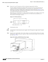
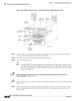
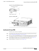
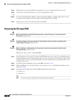
Chapter 4 Removal and Replacement Procedures Removing and Installing the DC-Input Power Supplies Step 5 Step 6 Step 7 Tighten the power supply captive installation screws. Remove the two screws that secure the outer terminal block cover, and remove the cover from the power supply. Remove the two screws that secure the left inner terminal block cover, remove the cover, and set it aside. Remove the one screw that secures the right inner terminal block cover, remove the cover, and set it aside. Note You must remove three terminal block covers for the 4000 W DC-input power supply. The left-side inner terminal block cover has two securing screws, and the right-side inner terminal block cover has one securing screw. Note You must install the plastic insulators that are shipped with the power supply. Step 8 Step 9 Step 10 Place both plastic insulators over the terminal areas, aligning the circular holes in insulating cover with terminal posts. The protective end flap on the plastic cover is opposite the wire entry area. The protective end flap must fold down and cover the open side of the terminal (opposite side from wire entry). Wrap the large perforated flaps around each pair of conductors, inserting each locking tab into the rear of the slot. Pull the tab until the cover is secured around the power cabling trim, and discard excess tab plastic. From the right side of the power supply, connect the DC-input wires to the right power supply terminal block (Figure 4-39) in this order: 1. Ground 2. Negative (-) 3. Positive (+) Note When you tighten the terminal nuts, make sure that they are snug. Do not overtighten them. Overtightening the terminal nuts can break the terminal block. (Maximum torque: 36 inch-pounds (4.07 Newton-meters). Step 11 From the right side of the power supply, connect the DC-input wires to the left power supply terminal block (Figure 4-39) in this order: 1. Negative (-) 2. Positive (+) Note When you tighten the terminal nuts, make sure that they are snug. Do not overtighten them. Overtightening the terminal nuts can break the terminal block. (Maximum torque: 36 inch-pounds.) OL-5781-04 Catalyst 6500 Series Switches Installation Guide 4-49
-
 1
1 -
2
-
3
-
4
-
5
-
6
-
7
-
8
-
9
-
10
-
11
-
12
-
13
-
14
-
15
-
16
-
17
-
18
-
19
-
20
-
21
-
22
-
23
-
24
-
25
-
26
-
27
-
28
-
29
-
30
-
31
-
32
-
33
-
34
-
35
-
36
-
37
-
38
-
39
-
40
-
41
-
42
-
43
-
44
-
45
-
46
-
47
-
48
-
49
-
50
-
51
-
52
-
53
-
54
-
55
-
56
-
57
-
58
-
59
-
60
-
61
-
62
-
63
-
64
-
65
-
66
-
67
-
68
-
69
-
70
-
71
-
72
-
73
-
74
-
75
-
76
-
77
-
78
-
79
-
80
-
81
-
82
-
83
-
84
-
85
-
86
-
87
-
88
-
89
-
90
-
91
-
92
-
93
-
94
-
95
-
96
-
97
-
98
-
99
-
100
-
101
-
102
-
103
-
104
-
105
-
106
-
107
-
108
-
109
-
110
-
111
-
112
-
113
-
114
-
115
-
116
-
117
-
118
-
119
-
120
-
121
-
122
-
123
-
124
-
125
-
126
-
127
-
128
-
129
-
130
-
131
-
132
-
133
-
134
-
135
-
136
-
137
-
138
-
139
-
140
-
141
-
142
-
143
-
144
-
145
-
146
-
147
-
148
-
149
-
150
-
151
-
152
-
153
-
154
-
155
-
156
-
157
-
158
-
159
-
160
-
161
-
162
-
163
-
164
-
165
-
166
-
167
-
168
-
169
-
170
-
171
-
172
-
173
-
174
-
175
-
176
-
177
-
178
-
179
-
180
-
181
-
182
-
183
-
 184
184 -
 185
185 -
 186
186 -
 187
187 -
 188
188 -
 189
189 -
 190
190 -
 191
191 -
 192
192 -
 193
193 -
 194
194 -
195
-
196
-
197
-
198
-
199
-
200
-
201
-
202
-
203
-
204
-
205
-
206
-
207
-
208
-
209
-
210
-
211
-
212
-
213
-
214
-
215
-
216
-
217
-
218
-
219
-
220
-
221
-
222
-
223
-
224
-
225
-
226
-
227
-
228
-
229
-
230
-
231
-
232
-
233
-
234
-
235
-
236
-
237
-
238
-
239
-
240
-
241
-
242
-
243
-
244
-
245
-
246
-
247
-
248
-
249
-
250
-
251
-
252
-
253
-
254
-
255
-
256
-
257
-
258
-
259
-
260
-
261
-
262
-
263
-
264
-
265
-
266
-
267
-
268
-
269
-
270
-
271
-
272
-
273
-
274
-
275
-
276
-
277
-
278
-
279
-
280
-
281
-
282
-
283
-
284
-
285
-
286
-
287
-
288
-
289
-
290
-
291
-
292
-
293
-
294
-
295
-
296
-
297
-
298
-
299
-
300
-
301
-
302
-
303
-
304
-
305
-
306
-
307
-
308
-
309
-
310
-
311
-
312
-
313
-
314
-
315
-
316
-
317
-
318
-
319
-
320
-
321
-
322
-
323
-
324
-
325
-
326
-
327
-
328
-
329
-
330
-
331
-
332
-
333
-
334
-
335
-
336
 |
 |