Cisco 6509 Installation Guide - Page 127
Connecting the System Ground
 |
UPC - 746320196077
View all Cisco 6509 manuals
Add to My Manuals
Save this manual to your list of manuals |
Page 127 highlights
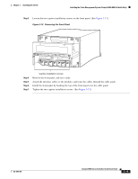
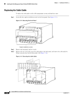
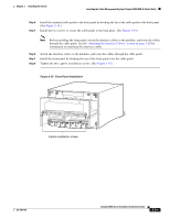
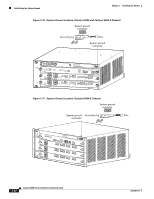
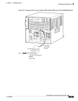
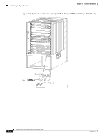
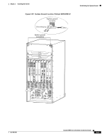
Chapter 3 Installing the Switch Establishing the System Ground Connecting the System Ground To attach the grounding lug and cable to the grounding pad, follow these steps: Step 1 Step 2 Step 3 Step 4 Use a wire-stripping tool to remove approximately 0.75 inch (19 mm) of the covering from the end of the grounding wire. Insert the stripped end of the grounding wire into the open end of the grounding lug. Crimp the grounding wire in the barrel of the grounding lug. Verify that the ground wire is securely attached to the ground lug. Locate and remove the adhesive label from the system grounding pad on the switch. The location of the system grounding pad differs among Catalyst 6500 series chassis. Refer to the figures listed to locate the system grounding pad on your chassis. • Catalyst 6503 and Catalyst 6503-E chassis-Figure 3-16 Caution The system (NEBS) ground serves as the primary safety ground for the Catalyst 6503 and Catalyst 6503-E chassis that are equipped with DC-input power supplies. You must install the system (NEBS) ground before you attach the source DC power cables to the DC PEM. If the Catalyst 6503 or Catalyst 6503-E chassis are already powered up, we recommend that you remove the source DC from the Catalyst 6503 and Catalyst 6503-E chassis before attaching the system (NEBS) ground. Step 5 • Catalyst 6504-E chassis-Figure 3-17 • Catalyst 6506, Catalyst 6509, and Catalyst 6509-NEB chassis-Figure 3-18 • Catalyst 6506-E, Catalyst 6509-E, and Catalyst 6513 chassis-Figure 3-19 • Catalyst 6509-NEB-A chassis-Figure 3-20 Place the grounding wire lug against the grounding pad, making sure that there is solid metal-to-metal contact. Note There are two system grounding pads on the Catalyst 6509-NEB-A switch chassis. One pad is located in the upper-left corner of the chassis, and the other is located in the upper-right corner of the chassis. Additionally, both system grounding pads have 3 M4 screw holes so that the system grounding lug can be installed either horizontally or vertically. Step 6 Step 7 Secure the grounding lug to the chassis with two M4 screws. Ensure that the grounding lug and the grounding wire will not interfere with other switch hardware or rack equipment. Prepare the other end of the grounding wire, and connect it to an appropriate grounding point in your site to ensure adequate earth ground for the switch. OL-5781-04 Catalyst 6500 Series Switches Installation Guide 3-23
-
 1
1 -
2
-
3
-
4
-
5
-
6
-
7
-
8
-
9
-
10
-
11
-
12
-
13
-
14
-
15
-
16
-
17
-
18
-
19
-
20
-
21
-
22
-
23
-
24
-
25
-
26
-
27
-
28
-
29
-
30
-
31
-
32
-
33
-
34
-
35
-
36
-
37
-
38
-
39
-
40
-
41
-
42
-
43
-
44
-
45
-
46
-
47
-
48
-
49
-
50
-
51
-
52
-
53
-
54
-
55
-
56
-
57
-
58
-
59
-
60
-
61
-
62
-
63
-
64
-
65
-
66
-
67
-
68
-
69
-
70
-
71
-
72
-
73
-
74
-
75
-
76
-
77
-
78
-
79
-
80
-
81
-
82
-
83
-
84
-
85
-
86
-
87
-
88
-
89
-
90
-
91
-
92
-
93
-
94
-
95
-
96
-
97
-
98
-
99
-
100
-
101
-
102
-
103
-
104
-
105
-
106
-
107
-
108
-
109
-
110
-
111
-
112
-
113
-
114
-
115
-
116
-
117
-
118
-
119
-
120
-
121
-
 122
122 -
 123
123 -
 124
124 -
 125
125 -
 126
126 -
 127
127 -
 128
128 -
 129
129 -
 130
130 -
 131
131 -
 132
132 -
133
-
134
-
135
-
136
-
137
-
138
-
139
-
140
-
141
-
142
-
143
-
144
-
145
-
146
-
147
-
148
-
149
-
150
-
151
-
152
-
153
-
154
-
155
-
156
-
157
-
158
-
159
-
160
-
161
-
162
-
163
-
164
-
165
-
166
-
167
-
168
-
169
-
170
-
171
-
172
-
173
-
174
-
175
-
176
-
177
-
178
-
179
-
180
-
181
-
182
-
183
-
184
-
185
-
186
-
187
-
188
-
189
-
190
-
191
-
192
-
193
-
194
-
195
-
196
-
197
-
198
-
199
-
200
-
201
-
202
-
203
-
204
-
205
-
206
-
207
-
208
-
209
-
210
-
211
-
212
-
213
-
214
-
215
-
216
-
217
-
218
-
219
-
220
-
221
-
222
-
223
-
224
-
225
-
226
-
227
-
228
-
229
-
230
-
231
-
232
-
233
-
234
-
235
-
236
-
237
-
238
-
239
-
240
-
241
-
242
-
243
-
244
-
245
-
246
-
247
-
248
-
249
-
250
-
251
-
252
-
253
-
254
-
255
-
256
-
257
-
258
-
259
-
260
-
261
-
262
-
263
-
264
-
265
-
266
-
267
-
268
-
269
-
270
-
271
-
272
-
273
-
274
-
275
-
276
-
277
-
278
-
279
-
280
-
281
-
282
-
283
-
284
-
285
-
286
-
287
-
288
-
289
-
290
-
291
-
292
-
293
-
294
-
295
-
296
-
297
-
298
-
299
-
300
-
301
-
302
-
303
-
304
-
305
-
306
-
307
-
308
-
309
-
310
-
311
-
312
-
313
-
314
-
315
-
316
-
317
-
318
-
319
-
320
-
321
-
322
-
323
-
324
-
325
-
326
-
327
-
328
-
329
-
330
-
331
-
332
-
333
-
334
-
335
-
336
 |
 |