Compaq Armada E700 Armada E700 - Page 118
€€Display Assembly
 |
View all Compaq Armada E700 manuals
Add to My Manuals
Save this manual to your list of manuals |
Page 118 highlights
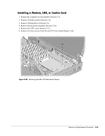
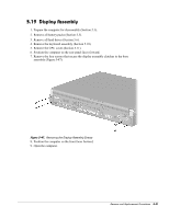
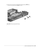
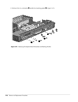
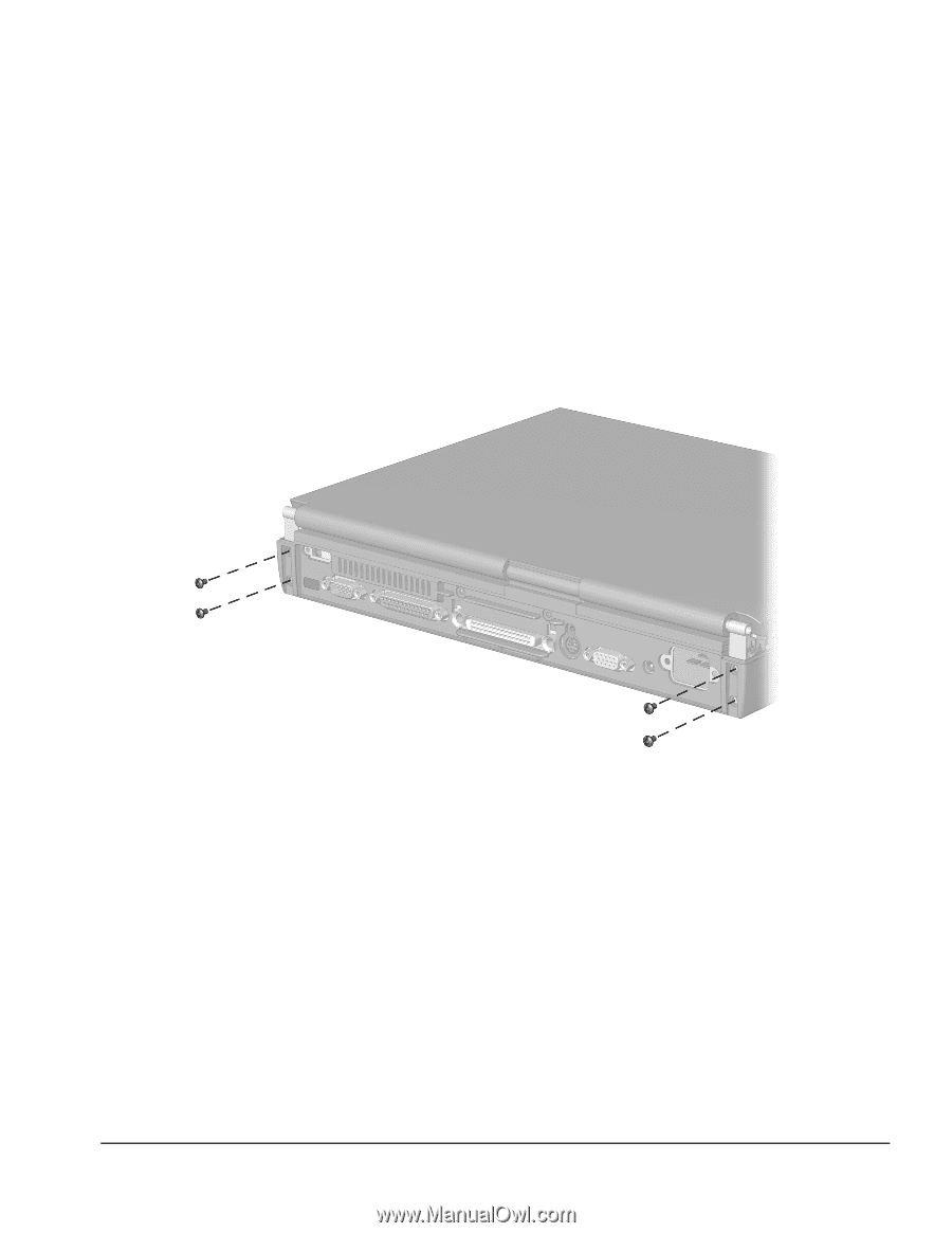
5.19 Display Assembly 1. Prepare the computer for disassembly (Section 5.3). 2. Remove all battery packs (Section 5.5). 3. Remove all hard drives (Section 5.6). 4. Remove the keyboard assembly (Section 5.10). 5. Remove the CPU cover (Section 5.11). 6. Position the computer so the rear panel faces forward. 7. Remove the four screws that secure the display assembly clutches to the base assembly (Figure 5-47). Figure 5-47. Removing the Display Assembly Screws 8. Position the computer so the front faces forward. 9. Open the computer. Remove and Replacement Procedures 5-51
-
 1
1 -
2
-
3
-
4
-
5
-
6
-
7
-
8
-
9
-
10
-
11
-
12
-
13
-
14
-
15
-
16
-
17
-
18
-
19
-
20
-
21
-
22
-
23
-
24
-
25
-
26
-
27
-
28
-
29
-
30
-
31
-
32
-
33
-
34
-
35
-
36
-
37
-
38
-
39
-
40
-
41
-
42
-
43
-
44
-
45
-
46
-
47
-
48
-
49
-
50
-
51
-
52
-
53
-
54
-
55
-
56
-
57
-
58
-
59
-
60
-
61
-
62
-
63
-
64
-
65
-
66
-
67
-
68
-
69
-
70
-
71
-
72
-
73
-
74
-
75
-
76
-
77
-
78
-
79
-
80
-
81
-
82
-
83
-
84
-
85
-
86
-
87
-
88
-
89
-
90
-
91
-
92
-
93
-
94
-
95
-
96
-
97
-
98
-
99
-
100
-
101
-
102
-
103
-
104
-
105
-
106
-
107
-
108
-
109
-
110
-
111
-
112
-
 113
113 -
 114
114 -
 115
115 -
 116
116 -
 117
117 -
 118
118 -
 119
119 -
 120
120 -
 121
121 -
 122
122 -
 123
123 -
124
-
125
-
126
-
127
-
128
-
129
-
130
-
131
-
132
-
133
-
134
-
135
-
136
-
137
-
138
-
139
-
140
-
141
-
142
-
143
-
144
-
145
-
146
-
147
-
148
-
149
-
150
-
151
-
152
-
153
 |
 |
Remove and Replacement Procedures
5-51
5.19
Display Assembly
1.
Prepare the computer for disassembly (Section 5.3).
2.
Remove all battery packs (Section 5.5).
3.
Remove all hard drives (Section 5.6).
4.
Remove the keyboard assembly (Section 5.10).
5.
Remove the CPU cover (Section 5.11).
6.
Position the computer so the rear panel faces forward.
7.
Remove the four screws that secure the display assembly clutches to the base
assembly (Figure 5-47).
Figure 5-47.
Removing the Display Assembly Screws
8.
Position the computer so the front faces forward.
9.
Open the computer.