Compaq Armada E700 Armada E700 - Page 69
€€Disassembly Reference Chart
 |
View all Compaq Armada E700 manuals
Add to My Manuals
Save this manual to your list of manuals |
Page 69 highlights
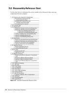
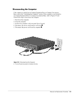
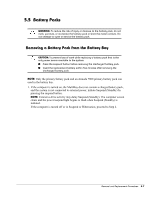
5.2 Disassembly Reference Chart Use the chart below to determine the section number to be referenced when removing components from the computer. 5.3 Preparing the Computer for Disassembly Undocking the Computer from the Compaq Expansion Base Undocking the Computer from the Compaq Convenience Base Disconnecting the Computer 5.4 Computer Feet 5.5 Battery Packs Removing a Battery Pack from the Battery Bay Removing a Battery Pack from the MultiBay Removing a MultiBay Battery Pack Removing a Dual-MultiBay Battery Pack Inserting a Battery Pack into the Battery Bay Inserting a MultiBay Battery Pack Inserting a Dual-MultiBay Battery Pack 5.6 Hard Drives Removing a Hard Drive from the Hard Drive Bay Inserting a Hard Drive into the Hard Drive Bay Removing a Hard Drive from the MultiBay Inserting a Hard Drive into the MultiBay 5.7 MultiBay Devices Removing MultiBay Devices Inserting MultiBay Devices 5.8 PC Cards Removing a PC Card Inserting a PC Card 5.9 Memory Expansion Removing the Memory Expansion Compartment Cover Removing a Memory Expansion Board Installing a Memory Expansion Board Replacing the Memory Expansion Compartment Cover 5.10 Keyboard Assembly 5.11 CPU Cover 5.12 Power Supply 5.13 Fan Assembly 5.14 Audio Board 5.15 Lithium Disk Cell Battery 5.16 Auxiliary Battery 5.17 Mini PCI Riser Board Installing a Modem, LAN, or Combo Board 5.18 USB Board 5.19 Display Assembly 5.20 System Board Figure 5-2. Computer Disassembly Sequence Chart 5-2 Removal and Replacement Procedures
-
 1
1 -
2
-
3
-
4
-
5
-
6
-
7
-
8
-
9
-
10
-
11
-
12
-
13
-
14
-
15
-
16
-
17
-
18
-
19
-
20
-
21
-
22
-
23
-
24
-
25
-
26
-
27
-
28
-
29
-
30
-
31
-
32
-
33
-
34
-
35
-
36
-
37
-
38
-
39
-
40
-
41
-
42
-
43
-
44
-
45
-
46
-
47
-
48
-
49
-
50
-
51
-
52
-
53
-
54
-
55
-
56
-
57
-
58
-
59
-
60
-
61
-
62
-
63
-
 64
64 -
 65
65 -
 66
66 -
 67
67 -
 68
68 -
 69
69 -
 70
70 -
 71
71 -
 72
72 -
 73
73 -
 74
74 -
75
-
76
-
77
-
78
-
79
-
80
-
81
-
82
-
83
-
84
-
85
-
86
-
87
-
88
-
89
-
90
-
91
-
92
-
93
-
94
-
95
-
96
-
97
-
98
-
99
-
100
-
101
-
102
-
103
-
104
-
105
-
106
-
107
-
108
-
109
-
110
-
111
-
112
-
113
-
114
-
115
-
116
-
117
-
118
-
119
-
120
-
121
-
122
-
123
-
124
-
125
-
126
-
127
-
128
-
129
-
130
-
131
-
132
-
133
-
134
-
135
-
136
-
137
-
138
-
139
-
140
-
141
-
142
-
143
-
144
-
145
-
146
-
147
-
148
-
149
-
150
-
151
-
152
-
153
 |
 |
