Dell OptiPlex 7000 Small Form Factor Service Manual
Dell OptiPlex 7000 Small Form Factor Manual
 |
View all Dell OptiPlex 7000 Small Form Factor manuals
Add to My Manuals
Save this manual to your list of manuals |
Dell OptiPlex 7000 Small Form Factor manual content summary:
- Dell OptiPlex 7000 Small Form Factor | Service Manual - Page 1
OptiPlex 7000 Small Form Factor Service Manual Regulatory Model: D17S Regulatory Type: D17S001 December 2022 Rev. A02 - Dell OptiPlex 7000 Small Form Factor | Service Manual - Page 2
tells you how to avoid the problem. WARNING: A WARNING indicates a potential for property damage, personal injury, or death. © 2021-2022 Dell Inc. or its subsidiaries. All rights reserved. Dell Technologies, Dell, and other trademarks are trademarks of Dell Inc. or its subsidiaries. Other trademarks - Dell OptiPlex 7000 Small Form Factor | Service Manual - Page 3
instructions...6 Before working inside your computer...6 Safety precautions...7 Electrostatic discharge-ESD protection...7 ESD field service 11 Major components of OptiPlex 7000 Small Form Factor 12 Side cover...14 -support bracket...36 Removing the bay-support bracket...36 Installing the bay-support - Dell OptiPlex 7000 Small Form Factor | Service Manual - Page 4
Installing the SD-card reader...39 Coin-cell battery...40 Removing the coin-cell battery...40 Installing the coin-cell battery...41 Power button...42 Removing the power button...42 Installing the power button...43 WLAN card...44 Removing the WLAN card...44 Installing the WLAN card...45 WLAN antenna - Dell OptiPlex 7000 Small Form Factor | Service Manual - Page 5
boot menu 100 System and setup password...101 Assigning a system setup password...101 Deleting or changing an existing system setup password 102 Clearing CMOS settings...102 Clearing BIOS (System Setup) and System passwords 102 Chapter 5: Troubleshooting...103 Dell SupportAssist Pre-boot System - Dell OptiPlex 7000 Small Form Factor | Service Manual - Page 6
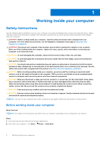
and the contacts. CAUTION: You should only perform troubleshooting and repairs as authorized or directed by the Dell technical assistance team. Damage due to servicing that is not authorized by Dell is not covered by your warranty. See the safety instructions that is shipped with the product or at - Dell OptiPlex 7000 Small Form Factor | Service Manual - Page 7
any disassembly instructions. Observe the of getting electrocuted. Standby power Dell products with standby power must be is done through the use of a field service electrostatic discharge (ESD) kit. When connecting a not be obvious, such as intermittent problems or a shortened product life span - Dell OptiPlex 7000 Small Form Factor | Service Manual - Page 8
damage to recognize and troubleshoot is the intermittent (also ESD mat, and the hardware is known as bonding. Use only Field Service kits with a wrist strap, mat, and bonding wire. Never use parts or parts to be returned to Dell, it is critical to place these parts in anti-static - Dell OptiPlex 7000 Small Form Factor | Service Manual - Page 9
wrist strap and protective anti-static mat at all times when servicing Dell products. In addition, it is critical that technicians keep sensitive parts separate from all insulator parts while performing service and that they use anti-static bags for transporting sensitive components. Transporting - Dell OptiPlex 7000 Small Form Factor | Service Manual - Page 10
ordered. Table 1. Screw list Component Solid-state drive Screw type M2x3 Quantity 1 Screw image Hard-drive and optical-drive #6-32 2 supporting bracket SD-card reader M3x5 1 WLAN card M2x3 1 Processor-fan and heat-sink Captive 4 assembly Voltage regulator heat-sink Captive - Dell OptiPlex 7000 Small Form Factor | Service Manual - Page 11
Table 2. CRU/FRU list OptiPlex 7000 Small Form Factor Side cover CRU component FRU component Front bezel Intrusion switch 2.5-inch hard drive 3.5-inch hard drive Optical drive Hard-drive and optical-drive bracket Hard-drive and optical-drive supporting bracket M.2 Solid-state drive WLAN - Dell OptiPlex 7000 Small Form Factor | Service Manual - Page 12
battery System fan Speaker VR heat-sink Power button Power supply unit Processor System board CRU component FRU component Major components of OptiPlex 7000 Small Form Factor The following image shows the major components of OptiPlex 7000 Small Form Factor. 12 Removing and installing components - Dell OptiPlex 7000 Small Form Factor | Service Manual - Page 13
Removing and installing components 13 - Dell OptiPlex 7000 Small Form Factor | Service Manual - Page 14
-drive bracket 6. WLAN card 8. System board 10. Front bezel 12. Power supply unit 14. Heat-sink and fan assembly 16. Processor NOTE: Dell provides a list of components and their part numbers for the original system configuration purchased. These parts are available according to warranty coverages - Dell OptiPlex 7000 Small Form Factor | Service Manual - Page 15
Installing the side cover Prerequisites If you are replacing a component, remove the existing component before performing the installation procedure. About this task The following images indicates the location of the side cover and provide a visual representation of the installation procedure. - Dell OptiPlex 7000 Small Form Factor | Service Manual - Page 16
Steps 1. Gently pry and release the front-bezel tabs sequentially from the top. 2. Rotate the front bezel outwards, away from the chassis, and remove the front bezel. Installing the front bezel Prerequisites If you are replacing a component, remove the existing component before performing the - Dell OptiPlex 7000 Small Form Factor | Service Manual - Page 17
Steps 1. Align and insert the front-bezel tabs with the slots on the chassis. 2. Rotate the front bezel towards the chassis and snap it into place. Next steps 1. Install the side cover. 2. Follow the procedure in after working inside your computer. Intrusion switch Removing the intrusion switch - Dell OptiPlex 7000 Small Form Factor | Service Manual - Page 18
Steps 1. Disconnect the intrusion-switch cable from the connector on the system board. 2. Slide the intrusion switch and lift it away from the computer. Installing the intrusion switch Prerequisites If you are replacing a component, remove the existing component before performing the installation - Dell OptiPlex 7000 Small Form Factor | Service Manual - Page 19
Steps 1. Slide the intrusion switch into the slot on the chassis. 2. Insert the connector from intrusion switch cable into the connector on the system board. Next steps 1. Install the side cover. 2. Follow the procedure in after working inside your computer. Hard drive Removing the 2.5-inch hard - Dell OptiPlex 7000 Small Form Factor | Service Manual - Page 20
About this task The following images indicate the location of the 2.5-inch hard drive and provide a visual representation of the removal procedure. 20 Removing and installing components - Dell OptiPlex 7000 Small Form Factor | Service Manual - Page 21
following images indicate the location of the 2.5-inch hard drive and provide a visual representation of the installation procedure. NOTE: For systems that support dual 2.5-inch hard drives, the second 2.5-inch hard drive can be mounted to the back of the hard-driver carrier. The installation steps - Dell OptiPlex 7000 Small Form Factor | Service Manual - Page 22
22 Removing and installing components - Dell OptiPlex 7000 Small Form Factor | Service Manual - Page 23
the slots on the chassis and snap the hard-drive carrier onto the disk-drive cage. NOTE: Use the arrows seen on the caddy as guides to identify the tabs on the tray. 5. Connect the hard-drive data and power cables to the connectors on the hard drive. Next steps 1. Install - Dell OptiPlex 7000 Small Form Factor | Service Manual - Page 24
Steps 1. Disconnect the hard-drive data and power cables from the connectors on the 3.5-inch hard drive. 2. Press the tab on the hard-drive carrier and lift the hard-drive carrier. 3. Slide the hard-drive carrier away from the chassis and lift hard-drive carrier out of the disk-drive cage. 4. Pry - Dell OptiPlex 7000 Small Form Factor | Service Manual - Page 25
Installing the 3.5-inch hard drive Prerequisites If you are replacing a component, remove the existing component before performing the installation procedure. About this task The following images indicate the location of the 3.5-inch hard drive and provide a visual representation of the installation - Dell OptiPlex 7000 Small Form Factor | Service Manual - Page 26
the slots on the chassis and snap the hard-drive carrier onto the disk-drive cage. NOTE: Use the arrows seen on the caddy as guides to identify the tabs on the tray. 4. Connect the hard-drive data and power cables to the connectors on the hard drive. Next steps 1. Install - Dell OptiPlex 7000 Small Form Factor | Service Manual - Page 27
About this task The following images indicate the location of the disk-drive cage and provide a visual representation of the removal procedure. Steps 1. Remove the hard-drive power and data cables that are routed via the locking mechanism. 2. Remove the cables from the routing points on the bracket - Dell OptiPlex 7000 Small Form Factor | Service Manual - Page 28
the disk-drive cage in place. 5. Route the optical drive's power and data cables through the routing guide on the disk-drive cage. 6. Route the hard-drive power and SATA cables through the routing guide on the lock. Next steps 1. Install the 3.5-inch hard-drive. 2. Install the 2.5-inch hard-drive - Dell OptiPlex 7000 Small Form Factor | Service Manual - Page 29
Optical drive Removing the optical drive Prerequisites 1. Follow the procedure in before working inside your computer. 2. Remove the side cover. 3. Remove the front bezel. 4. Remove the 2.5-inch hard-drive. 5. Remove the 3.5-inch hard-drive. 6. Remove the disk-drive cage. About this task The - Dell OptiPlex 7000 Small Form Factor | Service Manual - Page 30
Steps 1. Release the tab on the optical drive to release the optical drive from the disk-drive cage. 30 Removing and installing components - Dell OptiPlex 7000 Small Form Factor | Service Manual - Page 31
2. Slide the optical drive out of the disk-drive cage. Installing the optical-drive Prerequisites If you are replacing a component, remove the existing component before performing the installation procedure. About this task The following images show the optical-drive and provide a visual - Dell OptiPlex 7000 Small Form Factor | Service Manual - Page 32
Steps Slide the optical drive into the disk-drive cage until it snaps into place. 32 Removing and installing components - Dell OptiPlex 7000 Small Form Factor | Service Manual - Page 33
Next steps 1. Install the disk-drive cage. 2. Install the 3.5-inch hard-drive. 3. Install the 2.5-inch hard-drive. 4. Install the front bezel. 5. Install the side cover. 6. Follow the procedure in after working inside your computer. Solid-state drive Removing the M.2 2230 PCIe solid-state drive - Dell OptiPlex 7000 Small Form Factor | Service Manual - Page 34
Installing the M.2 2230 PCIe solid-state drive Prerequisites If you are replacing a component, remove the existing component before performing the installation procedure. About this task The following images indicate the location of the M.2 2230 PCIe solid-state drive and provide a visual - Dell OptiPlex 7000 Small Form Factor | Service Manual - Page 35
3. Remove the front bezel. 4. Remove the 2.5-inch hard-drive. 5. Remove the 3.5-inch hard-drive. 6. Remove the hard-drive and optical-drive bracket. About this task The following images indicate the location of the M.2 2280 PCIe solid-state drive and provide a visual representation of the removal - Dell OptiPlex 7000 Small Form Factor | Service Manual - Page 36
. 4. Install the front bezel. 5. Install the side cover. 6. Follow the procedure in after working inside your computer. Bay-support bracket Removing the bay-support bracket Prerequisites 1. Follow the procedure in before working inside your computer. 2. Remove the side cover. 3. Remove the front - Dell OptiPlex 7000 Small Form Factor | Service Manual - Page 37
bracket to free it from the front side of the chassis. 3. Lift and remove the bay-support bracket from the system. Installing the bay-support bracket Prerequisites If you are replacing a component, remove the existing component before performing the installation procedure. About this task The - Dell OptiPlex 7000 Small Form Factor | Service Manual - Page 38
on the slot on the chassis. 2. Replace the two (#6-32) screws that secures the bay-support bracket to the chassis. Next steps 1. Install the disk-drive cage. 2. Install the 3.5-inch hard-drive. 3. Install the 2.5-inch hard-drive. 4. Install the front bezel. 5. - Dell OptiPlex 7000 Small Form Factor | Service Manual - Page 39
the location of the SD-card reader and provide a visual representation of the removal procedure. Steps 1. Remove the power-supply cables from the routing guides on the SD-card reader bracket. 2. Remove the two screws (M3x5) that secure the SD-card bracket to the system board and the chassis - Dell OptiPlex 7000 Small Form Factor | Service Manual - Page 40
board and the chassis. 4. Route the power-supply cables through the routing guides on the SD-card reader bracket. Next steps 1. Install the hard-drive battery resets the BIOS setup program settings to default. It is recommended that you note the BIOS setup program settings before removing the - Dell OptiPlex 7000 Small Form Factor | Service Manual - Page 41
Steps 1. Push the coin-cell battery-release lever on the coin-cell battery socket to release the coin-cell battery out of the socket. 2. Remove the coin-cell battery. Installing the coin-cell battery Prerequisites If you are replacing a component, remove the existing component before performing the - Dell OptiPlex 7000 Small Form Factor | Service Manual - Page 42
Steps Insert the coin-cell battery into the socket with the positive side (+) label facing up and snap the battery in the socket. Next steps 1. Install the disk-drive cage. 2. Install the 3.5-inch hard-drive. 3. Install the 2.5-inch hard-drive. 4. Install the side cover. 5. Follow the procedure in - Dell OptiPlex 7000 Small Form Factor | Service Manual - Page 43
Steps 1. Disconnect the power-button cable from the connector on the system board. 2. Press the release tabs on the power-button head and push the power button through the slot on the chassis. 3. Remove the power button and its cable from the from the slot on the chassis. Installing the power button - Dell OptiPlex 7000 Small Form Factor | Service Manual - Page 44
Steps 1. Insert the power button and its cable into the slot on the chassis. 2. Press the power button until it is seated on the slot on the chassis. 3. Connect the power-button cable to the connector on the system board. Next steps 1. Install the disk-drive cage. 2. Install the 3.5-inch hard-drive. - Dell OptiPlex 7000 Small Form Factor | Service Manual - Page 45
6. Remove the disk-drive cage. About this task The following images indicate the location of the wireless card and provide a visual representation of the removal procedure. Steps 1. Remove the screw (M2x3) that secures the wireless card to the system board. 2. Slide and lift the wireless-card - Dell OptiPlex 7000 Small Form Factor | Service Manual - Page 46
Steps 1. Connect the antenna cables to the WLAN card. The following table provides the antenna-cable color scheme for the WLAN card of your computer. Table 3. Antenna-cable color scheme Connectors on the wireless card Main (white triangle) Auxiliary (black triangle) Antenna-cable color White Black - Dell OptiPlex 7000 Small Form Factor | Service Manual - Page 47
the location of the internal WLAN antenna and provide a visual representation of the removal procedure. Steps 1. Remove the antenna cables from the routing guides on the chassis. 2. Remove the two (M2x3) screws that secures the WLAN antenna to the chassis. 3. Lift and remove the WLAN antenna from - Dell OptiPlex 7000 Small Form Factor | Service Manual - Page 48
the location of the WLAN antenna and provides a visual representation of the installation procedure. Steps 1. Route the WLAN antenna cables through the routing guides on the chassis. 2. Place and align the screw holes on the WLAN antenna with the screw holes on the chassis 3. Replace the two - Dell OptiPlex 7000 Small Form Factor | Service Manual - Page 49
5. Remove the 3.5-inch hard-drive. 6. Remove the disk-drive cage. 7. Remove the WLAN card. About this task The following images indicate the location of the external WLAN antennas and provide a visual representation of the removal procedure. Steps 1. Remove the nut and washer from the two antenna - Dell OptiPlex 7000 Small Form Factor | Service Manual - Page 50
Installing the external WLAN antenna Prerequisites If you are replacing a component, remove the existing component before performing the installation procedure. About this task The following images indicate the location of the WLAN antennas and provide a visual representation of the installation - Dell OptiPlex 7000 Small Form Factor | Service Manual - Page 51
. NOTE: This step is only applicable when the system is being upgraded to have an external WLAN antenna. 2. Route the antenna cables through the routing guides on the system board. 3. Push the antenna-modules in to the slot on the back panel of the chassis. Removing and installing components 51 - Dell OptiPlex 7000 Small Form Factor | Service Manual - Page 52
4. Install the nut and washer to secure the antenna-modules to the chassis. Next steps 1. Install the disk-drive cage. 2. Install the WLAN card. 3. Install the 3.5-inch hard-drive. 4. Install the 2.5-inch hard-drive. 5. Install the front bezel. 6. Install the side cover. 7. Follow the procedure in - Dell OptiPlex 7000 Small Form Factor | Service Manual - Page 53
NOTE: Note the slot and the orientation of the memory module in order to replace it in the correct slot. Installing the memory Prerequisites If you are replacing a component, remove the existing component before performing the installation procedure. About this task The following images indicate the - Dell OptiPlex 7000 Small Form Factor | Service Manual - Page 54
Processor fan and heat-sink assembly Removing the processor fan and heat-sink assembly Prerequisites 1. Follow the procedure in before working inside your computer. 2. Remove the side cover. 3. Remove the front bezel. 4. Remove the disk-drive cage. About this task The following images indicate the - Dell OptiPlex 7000 Small Form Factor | Service Manual - Page 55
2. Loosen the four captive screws that secure the processor fan and heat-sink assembly to the system board. 3. Lift the processor fan and heat-sink assembly from the chassis. Installing the processor fan and heat-sink assembly Prerequisites If you are replacing a component, remove the existing - Dell OptiPlex 7000 Small Form Factor | Service Manual - Page 56
Next steps 1. Install the disk-drive cage. 2. Install the front bezel. 3. Install the side cover. 4. Follow the procedure in after working inside your computer. Voltage-regulator heat sink Removing the voltage-regulator heat sink Prerequisites 1. Follow the procedure in before working inside your - Dell OptiPlex 7000 Small Form Factor | Service Manual - Page 57
Installing the voltage-regulator heat sink Prerequisites If you are replacing a component, remove the existing component before performing the installation procedure. About this task The following image indicates the location of the voltage-regulator heat sink and provide a visual representation of - Dell OptiPlex 7000 Small Form Factor | Service Manual - Page 58
NOTE: The processor may become hot during normal operation. Allow sufficient time for the heat sink to cool before you touch it. About this task The following images indicate the location of the processor and provide a visual representation of the removal procedure. Steps 1. Press the release lever - Dell OptiPlex 7000 Small Form Factor | Service Manual - Page 59
Steps 1. Ensure that the release lever on the processor socket is fully extended in the open position. 2. Align the notches on the processor with the tabs on the processor socket and place the processor in the processor socket. NOTE: Ensure that the processor-cover notch is positioned underneath the - Dell OptiPlex 7000 Small Form Factor | Service Manual - Page 60
Steps 1. Using the tab, lift and open the PCIe door. 2. Push and hold the securing tab on the graphics-card slot and lift the graphics card from the PCIe x16 card slot. 3. Lift the graphics card off the system board. Installing the graphics card Prerequisites If you are replacing a component, remove - Dell OptiPlex 7000 Small Form Factor | Service Manual - Page 61
Steps 1. Align the graphics card with the PCIe x16 card slot on the system board. 2. Using the alignment post on the PCIe slot, connect the card in the connector and press down firmly. Ensure that the card is firmly seated. 3. Close the PCIe door. Next steps 1. Install the side cover. 2. Follow the - Dell OptiPlex 7000 Small Form Factor | Service Manual - Page 62
3. Remove the front bezel. 4. Remove the heat-sink and fan assembly. About this task The following images indicate the location of the PS2 module and provides a visual representation of the removal procedure. Steps 1. Lift the pull tab and open the expansion-card door. 2. Disconnect the PS2 module - Dell OptiPlex 7000 Small Form Factor | Service Manual - Page 63
3. Lift the PS2 module off the system board. Installing PS2 module Prerequisites If you are replacing a component, remove the existing component before performing the installation procedure. About this task The following images indicate the location of the PS2 module and provide a visual - Dell OptiPlex 7000 Small Form Factor | Service Manual - Page 64
Steps 1. Insert the PS2 module into its slot on the chassis. 2. Connect the PS2-module cable to the connector on the system board. 3. Close the expansion-card door, and press until it clicks into place. Next steps 1. Install the heat-sink and fan assembly. 2. Install the side cover. 64 Removing - Dell OptiPlex 7000 Small Form Factor | Service Manual - Page 65
3. Follow the procedure in after working inside your computer. Optional I/O modules (VGA/HDMI/DP/USB Type-C) Removing optional I/O module Prerequisites 1. Follow the procedure in before working inside your computer. 2. Remove the side cover. 3. Remove the front bezel. 4. Remove the heat-sink and fan - Dell OptiPlex 7000 Small Form Factor | Service Manual - Page 66
About this task The following images indicate the location of the optional I/O module and provide a visual representation of the installation procedure. Steps 1. Using a screwdriver, remove the bracket covering the I/O module slot. NOTE: This step is only for systems that are being upgraded with - Dell OptiPlex 7000 Small Form Factor | Service Manual - Page 67
2. Remove the side cover. 3. Remove the front bezel. 4. Remove the 2.5-inch hard-drive. 5. Remove the 3.5-inch hard-drive. 6. Remove the disk-drive cage. About this task The following image indicates the location of the chassis fan and provide a visual representation of the removal procedure. Steps - Dell OptiPlex 7000 Small Form Factor | Service Manual - Page 68
Steps 1. Insert the first two rubber grommets on the chassis fan. 2. Place the fan thought the chassis and push the rubber grommets downward until they are secured to the chassis. 3. Align the slots on the fan with the second set of holes on the chassis. 4. Route the rubber grommets through the - Dell OptiPlex 7000 Small Form Factor | Service Manual - Page 69
Steps 1. Disconnect the speaker cable from the connector on the system board. 2. Remove the speaker cable from the routing guides on the chassis. 3. Press the tab and slide the speaker along with the cable from the slot on the chassis. Installing the speaker Prerequisites If - Dell OptiPlex 7000 Small Form Factor | Service Manual - Page 70
Steps 1. Press and slide the speaker in the slot on the chassis until it snaps into place. 2. Route the speaker cable through the routing guide on the chassis. 3. Connect the speaker cable to the connector on the system board. Next steps 1. Install the side cover. 2. Follow the procedure in after - Dell OptiPlex 7000 Small Form Factor | Service Manual - Page 71
Steps 1. Disconnect the power-supply cables from the connectors on the system board. 2. Remove the power-supply cables from the routing guides on the chassis. 3. Remove the three screws (M6-32) that secure the power-supply unit to the chassis. 4. Slide and lift the power-supply unit - Dell OptiPlex 7000 Small Form Factor | Service Manual - Page 72
chassis. 2. Replace the three (M6-32) screws to secure the power-supply unit to the chassis. 3. Route the power-supply cables through the routing guides on the chassis. 4. Connect the power-supply cables to the connectors on the system board. Next steps 1. Install the disk-drive cage. 2. Install the - Dell OptiPlex 7000 Small Form Factor | Service Manual - Page 73
System board System board r The following image indicates the slots and connectors on your system board: 1. Intrusion switch cable 2. Processor-power cables 3. Processor fan connector 4. UDIMM slots From the left (a>b>c>d): DIMM 3 DIMM 1 DIMM 4 DIMM 2 5. Coin-cell battery socket 6. Power-button - Dell OptiPlex 7000 Small Form Factor | Service Manual - Page 74
19. M.2 2230/2280 solid-state drive slot 20. Processor socket 21. I/O cable Removing the system board Prerequisites 1. Follow the procedure in before working inside your computer. 2. Remove the side cover. 3. Remove the front bezel. 4. Remove the 2.5-inch hard-drive. 5. Remove the 3.5-inch hard- - Dell OptiPlex 7000 Small Form Factor | Service Manual - Page 75
Removing and installing components 75 - Dell OptiPlex 7000 Small Form Factor | Service Manual - Page 76
Steps 1. Remove the screw (6-32) that secures the front I/O bracket to the chassis. 2. Rotate and remove the front I/O-bracket from the chassis 3. Disconnect all the cables that are connected to the system board. 4. Remove the four screws (#6-32) that secure the system board to the chassis. 5. Free - Dell OptiPlex 7000 Small Form Factor | Service Manual - Page 77
Removing and installing components 77 - Dell OptiPlex 7000 Small Form Factor | Service Manual - Page 78
78 Removing and installing components - Dell OptiPlex 7000 Small Form Factor | Service Manual - Page 79
Steps 1. Align and lower the system board into the system until the stand-off points at the back of the system board align with those on the chassis. 2. Replace the four (#6-32) screws to secure the system board to the chassis. 3. Route and connect all the cables that you disconnected from the - Dell OptiPlex 7000 Small Form Factor | Service Manual - Page 80
3 Drivers and downloads When troubleshooting, downloading or installing drivers it is recommended that you read the Dell Knowledge Based article, Drivers and Downloads FAQ 000123347. 80 Drivers and downloads - Dell OptiPlex 7000 Small Form Factor | Service Manual - Page 81
of hard drive installed, and enabling or disabling base devices. Entering BIOS setup program About this task Turn on (or restart) your computer and press F2 immediately. Navigation keys NOTE: For most of the System Setup options, changes that you make are recorded but do not take effect - Dell OptiPlex 7000 Small Form Factor | Service Manual - Page 82
listed in this section may or may not appear. Table 5. System setup options-System information menu General-System Information System Information BIOS Version Displays the BIOS version number. Service Tag Displays the Service Tag of the computer. Asset Tag Displays the Asset Tag of the - Dell OptiPlex 7000 Small Form Factor | Service Manual - Page 83
time in HH:MM:SS AM/PM format. Table 6. System setup options-System Configuration menu System Configuration Integrated NIC Controls the on-board SMART Reporting during system startup. USB Configuration Enable USB Boot Support Enable or disable booting from USB mass storage devices such as - Dell OptiPlex 7000 Small Form Factor | Service Manual - Page 84
the BIOS module interface of the optional Computrace(R) Service from Absolute Software. Admin Setup Lockout Enable to prevent users from entering Setup when an Admin Password is set. Master Password Lockout Disables the master password support. Hard Disk passwords need to be cleared before - Dell OptiPlex 7000 Small Form Factor | Service Manual - Page 85
custom values for expert key management. Table 10. System setup options-Intel Software Guard Extensions menu Intel Software Guard is set to Everyday, Weekdays or Selected Days. Default: Disabled. USB Wake Support Deep Sleep Control Wake on LAN/WLAN Block sleep POST Behavior Numlock LED Keyboard - Dell OptiPlex 7000 Small Form Factor | Service Manual - Page 86
Table 15. System setup options-SupportAssist System Resolution menu SupportAssist System Resolution Auto OS Recovery Threshold Control the automatic boot flow for SupportAssist System Resolution Console and for Dell OS Recovery tool. Overview This section provides hardware specification for the - Dell OptiPlex 7000 Small Form Factor | Service Manual - Page 87
Description ● Signed Firmware Update - This helps to verify that only Dell Signed and released BIOS can be installed on the computer. The the computer. ● Native Resolution - This field mentions the native video resolution supported on the computer. ● Video BIOS Version - The version of the BIOS - Dell OptiPlex 7000 Small Form Factor | Service Manual - Page 88
(Enabled by default) ● UEFI Boot Drive (Enabled by default) ● Add Boot option - Allows the user to manually add a Boot path. Secure Digital(SD) Card Boot This section contains a toggle switch that allows the user to are as below: ● PK (Selected by default) ● KEK ● db ● dbx 88 BIOS setup - Dell OptiPlex 7000 Small Form Factor | Service Manual - Page 89
by default): ● Enable Front USB Ports ● Enable Rear USB Ports ● Enable USB Boot Support This section allows the user to manually enable the 4 USB ports on the front bezel (All USB ports are enabled by default the optional dust filter. BIOS will generate a pre-boot reminder BIOS setup 89 - Dell OptiPlex 7000 Small Form Factor | Service Manual - Page 90
. The following options are available: ● Disabled - SATA controllers are disabled. ● AHCI - SATA is configured in AHCI mode. ● RAID On - SATA is setup to support RAID (Intel Rapid Storage Technology). (Selected by default) This section allows the user to enable or disable the onboard drives on the - Dell OptiPlex 7000 Small Form Factor | Service Manual - Page 91
which allows the user to enable/disable Multi-Display. (disabled by default). This feature is only supported on Windows 7 and above. This section allows the user to select the video controller for the user to enable or disable installation of UEFI networking protocols. (ON by default) BIOS setup 91 - Dell OptiPlex 7000 Small Form Factor | Service Manual - Page 92
Options USB Wake Support Enable USB Wake Support AC Behavior Active State Power Management (ASPM) Block Sleep 92 BIOS setup Description This section Boot URL from DHCP(Dynamic Host Configuration Protocol) Selected by default. ● Manual Mode - HTTP(s) Boot reads Boot URL provided by the user. This - Dell OptiPlex 7000 Small Form Factor | Service Manual - Page 93
contains a toggle switch to allow the user to enable or disable Intel Speed Shift Technology support. This feature enables the operating system to select appropriate processor performance automatically (ON by default is encrypted by the TME block attached to the memory controller BIOS setup 93 - Dell OptiPlex 7000 Small Form Factor | Service Manual - Page 94
on password settings. 94 BIOS setup Description This field controls the chassis interface of the optional Absolute Persistence Module service from Absolute Software. The options available allows the user to choose between dynamic and manual shutter control: ● Dynamic Shutter - Camera shutter - Dell OptiPlex 7000 Small Form Factor | Service Manual - Page 95
switch which allows the administrator to control how users can or cannot access BIOS setup (OFF by default). This section contains a toggle switch which allows the user to disable active password support (OFF by default). Update Recovery This section provides details on Update Recovery settings - Dell OptiPlex 7000 Small Form Factor | Service Manual - Page 96
Dell Auto OS Recovery Threshold Dell Auto OS Recovery Threshold System Management This section provides System Management settings. Table 26. System Management Options Service Tag Service the user to enable or disable BIOSConnect setup to attempt cloud Service OS recovery if the main operating system - Dell OptiPlex 7000 Small Form Factor | Service Manual - Page 97
. This field contains a toggle switch(ON/OFF) to allow the user to decide if the Numlock LED should be on when the system boots. BIOS setup 97 - Dell OptiPlex 7000 Small Form Factor | Service Manual - Page 98
provides Performance settings. Table 29. Performance Options Multi-Core Support Active Cores Intel SpeedStep Enable Intel SpeedStep Technology C-States Control Hyper-Threading Technology Dynamic Tuning: Machine Learning 98 BIOS setup Description This field contains a toggle switch to enable or - Dell OptiPlex 7000 Small Form Factor | Service Manual - Page 99
.dell.com/support. 2. Click Product support. In the Search support box, enter the Service Tag of your computer, and then click Search. NOTE: If you do not have the Service Tag, use the SupportAssist feature to automatically identify your computer. You can also use the product ID or manually browse - Dell OptiPlex 7000 Small Form Factor | Service Manual - Page 100
, search in the Knowledge Base Resource at www.dell.com/support. 3. Copy the BIOS setup program file to the bootable USB drive. 4. Connect Menu. 7. Type the BIOS setup program filename and press Enter. The BIOS Update Utility appears. 8. Follow the on-screen instructions to complete the BIOS update. - Dell OptiPlex 7000 Small Form Factor | Service Manual - Page 101
system. Password that you must enter to access and make changes to the BIOS settings of your computer. You can create a system password and a setup password to secure your computer. CAUTION: The password features provide a basic level of security for the data on your computer. CAUTION: Anyone can - Dell OptiPlex 7000 Small Form Factor | Service Manual - Page 102
4. Replace the coin-cell battery. 5. Replace the side cover. Clearing BIOS (System Setup) and System passwords About this task To clear the system or BIOS passwords, contact Dell technical support as described at www.dell.com/contactdell. NOTE: For information on how to reset Windows or application - Dell OptiPlex 7000 Small Form Factor | Service Manual - Page 103
inform you of problems encountered during testing NOTE: Some tests for specific devices require user interaction. Always ensure that you are present at the computer terminal when the diagnostic tests are performed. For more information, see https://www.dell.com/support - Dell OptiPlex 7000 Small Form Factor | Service Manual - Page 104
SPI Flash Failure CPU failure ● Run the Dell Support Assist/Dell Diagnostics tool. ● If problem persists, replace the system board. System board failure (included ● BIOS corruption or ROM ● error) Flash latest BIOS version If problem persists, replace the system board. No memory - Dell OptiPlex 7000 Small Form Factor | Service Manual - Page 105
problem Support website to troubleshoot and fix your computer when it fails to boot into their primary operating system due to software or hardware failures. For more information about the Dell SupportAssist OS Recovery, see Dell SupportAssist OS Recovery User's Guide at www.dell ● Service Tag setup - Dell OptiPlex 7000 Small Form Factor | Service Manual - Page 106
troubleshoot and fix problems that may occur with Windows. Dell proposes multiple options for recovering Windows operating system on your Dell PC. For more information. see Dell provides the instructions on how to conduct a WiFi power cycle: NOTE: Some ISPs (Internet Service Providers) provide - Dell OptiPlex 7000 Small Form Factor | Service Manual - Page 107
about your computer through videos, manuals and documents. Your Dell computer is uniquely identified by a Service Tag or Express Service Code. To view relevant support resources for your Dell computer, enter the Service Tag or Express Service Code at www.dell.com/support. For more information on
-
 1
1 -
 2
2 -
 3
3 -
 4
4 -
 5
5 -
 6
6 -
 7
7 -
8
-
9
-
10
-
11
-
12
-
13
-
14
-
15
-
16
-
17
-
18
-
19
-
20
-
21
-
22
-
23
-
24
-
25
-
26
-
27
-
28
-
29
-
30
-
31
-
32
-
33
-
34
-
35
-
36
-
37
-
38
-
39
-
40
-
41
-
42
-
43
-
44
-
45
-
46
-
47
-
48
-
49
-
50
-
51
-
52
-
53
-
54
-
55
-
56
-
57
-
58
-
59
-
60
-
61
-
62
-
63
-
64
-
65
-
66
-
67
-
68
-
69
-
70
-
71
-
72
-
73
-
74
-
75
-
76
-
77
-
78
-
79
-
80
-
81
-
82
-
83
-
84
-
85
-
86
-
87
-
88
-
89
-
90
-
91
-
92
-
93
-
94
-
95
-
96
-
97
-
98
-
99
-
100
-
101
-
102
-
103
-
104
-
105
-
106
-
107
 |
 |

OptiPlex 7000 Small Form Factor
Service Manual
Regulatory Model: D17S
Regulatory Type: D17S001
December 2022
Rev. A02