Dell PowerStore 5000X EMC PowerStore Installation and Service Guide - Page 90
Expansion enclosure service procedures, Add a drive in a 25-drive expansion enclosure
 |
View all Dell PowerStore 5000X manuals
Add to My Manuals
Save this manual to your list of manuals |
Page 90 highlights
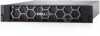
3 Expansion enclosure service procedures The expansion enclosure contains customer-replaceable components. Follow these procedures to safely replace a failed component. NOTE: Review the information in Safety precautions for handling replaceable units on page 106 before handling replaceable parts. Topics: • Add a drive in a 25-drive expansion enclosure • Replace a faulted drive in a 25-drive expansion enclosure • Replace a link control card in a 25-drive expansion enclosure • Replace a power/cooling module in a 25-drive expansion enclosure Add a drive in a 25-drive expansion enclosure Take the following actions to add a new drive to a 25-drive expansion enclosure. Removing the front bezel About this task NOTE: Remove the front bezel of the expansion enclosure to gain access to the drives. The bezel is required for EMI compliance when the enclosure is powered up. Remove it only to replace or add a drive. Steps 1. If the bezel has a lock, insert the key that shipped with your enclosure into the lock, and turn the key to unlock the bezel. 2. Press the two latch buttons on the bezel surface to release the bezel from the cabinet. 3. Pull the bezel off the cabinet, and put it on a clean, static-free surface. CL5261 Figure 117. Removing the front bezel 90 Expansion enclosure service procedures
-
 1
1 -
2
-
3
-
4
-
5
-
6
-
7
-
8
-
9
-
10
-
11
-
12
-
13
-
14
-
15
-
16
-
17
-
18
-
19
-
20
-
21
-
22
-
23
-
24
-
25
-
26
-
27
-
28
-
29
-
30
-
31
-
32
-
33
-
34
-
35
-
36
-
37
-
38
-
39
-
40
-
41
-
42
-
43
-
44
-
45
-
46
-
47
-
48
-
49
-
50
-
51
-
52
-
53
-
54
-
55
-
56
-
57
-
58
-
59
-
60
-
61
-
62
-
63
-
64
-
65
-
66
-
67
-
68
-
69
-
70
-
71
-
72
-
73
-
74
-
75
-
76
-
77
-
78
-
79
-
80
-
81
-
82
-
83
-
84
-
 85
85 -
 86
86 -
 87
87 -
 88
88 -
 89
89 -
 90
90 -
 91
91 -
 92
92 -
 93
93 -
 94
94 -
 95
95 -
96
-
97
-
98
-
99
-
100
-
101
-
102
-
103
-
104
-
105
-
106
-
107
-
108
-
109
-
110
-
111
-
112
-
113
-
114
-
115
-
116
-
117
-
118
-
119
-
120
-
121
-
122
-
123
-
124
-
125
-
126
-
127
-
128
-
129
 |
 |
