HP 1200 Service Manual - Page 69
Printer paper-feed system, Step 1
 |
UPC - 637836445790
View all HP 1200 manuals
Add to My Manuals
Save this manual to your list of manuals |
Page 69 highlights
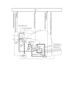
Printer paper-feed system Step 1 The main input tray and the priority input tray merge into one, main input area. Media placed in any of these areas enables the paper-out sensor (PS201), which informs the ECU that media is present. The following steps occur when the printer receives a print job: Step 2 The ECU enables the laser/scanner assembly and the motor. Paper motion begins when the ECU energizes the solenoid (SL001). Step 3 The paper pickup roller rotates once. The paper lift plate pushes the media against the pickup roller. Step 4 The pickup roller grabs the top sheet and advances it to the feed assembly drive rollers. To ensure that only one sheet is fed, a main separation pad and two subpads hold the remainder of the stack in place. Step 5 The feed assembly drive rollers advance the media to the paper top sensor (PS402). This sensor informs the ECU of the exact location of the leading edge of media, so that the image being written on the photosensitive drum can be precisely positioned on the page. Step 6 The feed assembly drive rollers then advance the media to the transfer area where the toner image on the photosensitive drum is transferred to media. Step 7 After the image is transferred, the media enters the fuser assembly where heat from the fuser and pressure from the pressure roller permanently bond the toner image to media. The paper delivery sensor (PS401) determines that media has successfully moved out of the fusing area. Step 8 The fuser assembly exit rollers deliver media to either the paper output bin or the straight-through output path, depending upon the position of the straight-through output path door. EN Printer functions 67
-
 1
1 -
2
-
3
-
4
-
5
-
6
-
7
-
8
-
9
-
10
-
11
-
12
-
13
-
14
-
15
-
16
-
17
-
18
-
19
-
20
-
21
-
22
-
23
-
24
-
25
-
26
-
27
-
28
-
29
-
30
-
31
-
32
-
33
-
34
-
35
-
36
-
37
-
38
-
39
-
40
-
41
-
42
-
43
-
44
-
45
-
46
-
47
-
48
-
49
-
50
-
51
-
52
-
53
-
54
-
55
-
56
-
57
-
58
-
59
-
60
-
61
-
62
-
63
-
 64
64 -
 65
65 -
 66
66 -
 67
67 -
 68
68 -
 69
69 -
 70
70 -
 71
71 -
 72
72 -
 73
73 -
 74
74 -
75
-
76
-
77
-
78
-
79
-
80
-
81
-
82
-
83
-
84
-
85
-
86
-
87
-
88
-
89
-
90
-
91
-
92
-
93
-
94
-
95
-
96
-
97
-
98
-
99
-
100
-
101
-
102
-
103
-
104
-
105
-
106
-
107
-
108
-
109
-
110
-
111
-
112
-
113
-
114
-
115
-
116
-
117
-
118
-
119
-
120
-
121
-
122
-
123
-
124
-
125
-
126
-
127
-
128
-
129
-
130
-
131
-
132
-
133
-
134
-
135
-
136
-
137
-
138
-
139
-
140
-
141
-
142
-
143
-
144
-
145
-
146
-
147
-
148
-
149
-
150
-
151
-
152
-
153
-
154
-
155
-
156
-
157
-
158
-
159
-
160
-
161
-
162
-
163
-
164
-
165
-
166
-
167
-
168
-
169
-
170
-
171
-
172
-
173
-
174
-
175
-
176
-
177
-
178
-
179
-
180
-
181
-
182
-
183
-
184
-
185
-
186
-
187
-
188
-
189
-
190
-
191
-
192
-
193
-
194
-
195
-
196
-
197
-
198
-
199
-
200
-
201
-
202
-
203
-
204
-
205
-
206
-
207
-
208
 |
 |
