HP 1200 Service Manual - Page 90
Control panel assembly, Removing the control panel
 |
UPC - 637836445790
View all HP 1200 manuals
Add to My Manuals
Save this manual to your list of manuals |
Page 90 highlights
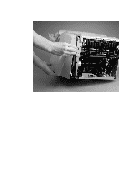
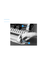
Note Control panel assembly 1 Remove the left side, back, right side, and top covers (see pages 80 through 87). 2 Disconnect the control panel cable (callout 1) from the formatter. 3 Remove two screws (callout 2 and callout 3) from the top of the control panel assembly. The first screw (callout 2) secures the control panel casing, and the second screw (callout 3) secures the internal bracket. Be sure to hold the assembly together as you remove it. Rotate the control panel assembly toward the front of the printer to release the tab (callout 4). 4 Remove the control panel assembly. 2 23 21 24 Figure 32. Removing the control panel 88 Chapter 5 - Removal and replacement EN
-
 1
1 -
2
-
3
-
4
-
5
-
6
-
7
-
8
-
9
-
10
-
11
-
12
-
13
-
14
-
15
-
16
-
17
-
18
-
19
-
20
-
21
-
22
-
23
-
24
-
25
-
26
-
27
-
28
-
29
-
30
-
31
-
32
-
33
-
34
-
35
-
36
-
37
-
38
-
39
-
40
-
41
-
42
-
43
-
44
-
45
-
46
-
47
-
48
-
49
-
50
-
51
-
52
-
53
-
54
-
55
-
56
-
57
-
58
-
59
-
60
-
61
-
62
-
63
-
64
-
65
-
66
-
67
-
68
-
69
-
70
-
71
-
72
-
73
-
74
-
75
-
76
-
77
-
78
-
79
-
80
-
81
-
82
-
83
-
84
-
 85
85 -
 86
86 -
 87
87 -
 88
88 -
 89
89 -
 90
90 -
 91
91 -
 92
92 -
 93
93 -
 94
94 -
 95
95 -
96
-
97
-
98
-
99
-
100
-
101
-
102
-
103
-
104
-
105
-
106
-
107
-
108
-
109
-
110
-
111
-
112
-
113
-
114
-
115
-
116
-
117
-
118
-
119
-
120
-
121
-
122
-
123
-
124
-
125
-
126
-
127
-
128
-
129
-
130
-
131
-
132
-
133
-
134
-
135
-
136
-
137
-
138
-
139
-
140
-
141
-
142
-
143
-
144
-
145
-
146
-
147
-
148
-
149
-
150
-
151
-
152
-
153
-
154
-
155
-
156
-
157
-
158
-
159
-
160
-
161
-
162
-
163
-
164
-
165
-
166
-
167
-
168
-
169
-
170
-
171
-
172
-
173
-
174
-
175
-
176
-
177
-
178
-
179
-
180
-
181
-
182
-
183
-
184
-
185
-
186
-
187
-
188
-
189
-
190
-
191
-
192
-
193
-
194
-
195
-
196
-
197
-
198
-
199
-
200
-
201
-
202
-
203
-
204
-
205
-
206
-
207
-
208
 |
 |

88
Chapter 5 - Removal and replacement
EN
Control panel assembly
1
Remove the left side, back, right side, and top covers (see pages
80 through 87).
2
Disconnect the control panel cable (callout 1) from the formatter.
3
Remove two screws (callout 2 and callout 3) from the top of the
control panel assembly.
Note
The first screw (callout 2) secures the control panel casing, and the
second screw (callout 3) secures the internal bracket. Be sure to hold
the assembly together as you remove it.
Rotate the control panel assembly toward the front of the printer to
release the tab (callout 4).
4
Remove the control panel assembly.
Figure 32.
Removing the control panel
2
2
2
2
1
3
4
2