HP 1200 Service Manual - Page 72
Solenoid, photosensors, and switches
 |
UPC - 637836445790
View all HP 1200 manuals
Add to My Manuals
Save this manual to your list of manuals |
Page 72 highlights
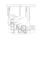
Solenoid, photosensors, and switches The following figure shows the locations of the solenoid, photosensors, and switches. 1 6 2 3 4 7 5 Figure 20. Solenoid, photosensors, and switches 1 Paper delivery sensor (PS401) senses when paper has successfully moved out of the fusing area. 2 Power switch. Note Products sold in North America do not have power switches. 3 Paper top sensor (PS402) detects the leading and trailing edges of the paper. It synchronizes the photosenstive drum and the top of the paper. 4 Engine test switch (SW201); see "Engine test" on page 149 for an explanation of the switch. 5 Door-open switch (SW301) detects whether or not the printer door is closed and the toner cartridge is present. Printing cannot continue until the printer door is closed and the toner cartridge is in its correct position. 6 Solenoid (SL001) enables the pickup roller. 7 Paper-out sensor (PS201) senses when paper is in the main input tray or the priority input tray. 70 Chapter 4 - Operational overview EN
-
 1
1 -
2
-
3
-
4
-
5
-
6
-
7
-
8
-
9
-
10
-
11
-
12
-
13
-
14
-
15
-
16
-
17
-
18
-
19
-
20
-
21
-
22
-
23
-
24
-
25
-
26
-
27
-
28
-
29
-
30
-
31
-
32
-
33
-
34
-
35
-
36
-
37
-
38
-
39
-
40
-
41
-
42
-
43
-
44
-
45
-
46
-
47
-
48
-
49
-
50
-
51
-
52
-
53
-
54
-
55
-
56
-
57
-
58
-
59
-
60
-
61
-
62
-
63
-
64
-
65
-
66
-
 67
67 -
 68
68 -
 69
69 -
 70
70 -
 71
71 -
 72
72 -
 73
73 -
 74
74 -
 75
75 -
 76
76 -
 77
77 -
78
-
79
-
80
-
81
-
82
-
83
-
84
-
85
-
86
-
87
-
88
-
89
-
90
-
91
-
92
-
93
-
94
-
95
-
96
-
97
-
98
-
99
-
100
-
101
-
102
-
103
-
104
-
105
-
106
-
107
-
108
-
109
-
110
-
111
-
112
-
113
-
114
-
115
-
116
-
117
-
118
-
119
-
120
-
121
-
122
-
123
-
124
-
125
-
126
-
127
-
128
-
129
-
130
-
131
-
132
-
133
-
134
-
135
-
136
-
137
-
138
-
139
-
140
-
141
-
142
-
143
-
144
-
145
-
146
-
147
-
148
-
149
-
150
-
151
-
152
-
153
-
154
-
155
-
156
-
157
-
158
-
159
-
160
-
161
-
162
-
163
-
164
-
165
-
166
-
167
-
168
-
169
-
170
-
171
-
172
-
173
-
174
-
175
-
176
-
177
-
178
-
179
-
180
-
181
-
182
-
183
-
184
-
185
-
186
-
187
-
188
-
189
-
190
-
191
-
192
-
193
-
194
-
195
-
196
-
197
-
198
-
199
-
200
-
201
-
202
-
203
-
204
-
205
-
206
-
207
-
208
 |
 |
