HP A4500A Hardware Manual - rp24xx, Customer Viewable - Page 128
Installing the CPU, Step 1.
 |
View all HP A4500A manuals
Add to My Manuals
Save this manual to your list of manuals |
Page 128 highlights
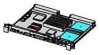
Adding CPUs and Socket Cleaning 14. Inspect the CPU socket on the system board for broken buttons or other debris. Note that it is normal for a certain amount of residue to be left behind when removing the CPU assembly. If broken buttons are observed, remove them carefully with the IPA lint free wipe. Take care to contain the debris and completely remove them from the system board socket. 15. Vacuum the system board socket site, being careful not to introduce contaminates in the process. 16. Carefully clean the system board socket with the IPA lint free wipe. 17. Install the CPU assembly into the appropriate CPU socket on the system board. Installing the CPU Install CPUs according to the procedure listed below: Step 1. Carefully align the CPU notches with the socket notches and set the CPU in place. Step 2. Tighten the four captive T-15 mounting screws that hold the CPU in place. NOTE Tighten the four CPU mounting screws a little at a time, in a cross pattern (1, 3, 2, 4), until they are all tight. The following picture shows both CPUs installed in a server. 136 Chapter
-
 1
1 -
2
-
3
-
4
-
5
-
6
-
7
-
8
-
9
-
10
-
11
-
12
-
13
-
14
-
15
-
16
-
17
-
18
-
19
-
20
-
21
-
22
-
23
-
24
-
25
-
26
-
27
-
28
-
29
-
30
-
31
-
32
-
33
-
34
-
35
-
36
-
37
-
38
-
39
-
40
-
41
-
42
-
43
-
44
-
45
-
46
-
47
-
48
-
49
-
50
-
51
-
52
-
53
-
54
-
55
-
56
-
57
-
58
-
59
-
60
-
61
-
62
-
63
-
64
-
65
-
66
-
67
-
68
-
69
-
70
-
71
-
72
-
73
-
74
-
75
-
76
-
77
-
78
-
79
-
80
-
81
-
82
-
83
-
84
-
85
-
86
-
87
-
88
-
89
-
90
-
91
-
92
-
93
-
94
-
95
-
96
-
97
-
98
-
99
-
100
-
101
-
102
-
103
-
104
-
105
-
106
-
107
-
108
-
109
-
110
-
111
-
112
-
113
-
114
-
115
-
116
-
117
-
118
-
119
-
120
-
121
-
122
-
 123
123 -
 124
124 -
 125
125 -
 126
126 -
 127
127 -
 128
128 -
 129
129 -
 130
130 -
 131
131 -
 132
132 -
 133
133 -
134
-
135
-
136
-
137
-
138
-
139
-
140
-
141
-
142
-
143
-
144
-
145
-
146
-
147
-
148
-
149
-
150
-
151
-
152
-
153
-
154
-
155
-
156
-
157
-
158
-
159
-
160
-
161
-
162
-
163
-
164
-
165
-
166
-
167
-
168
-
169
-
170
-
171
-
172
-
173
-
174
-
175
-
176
-
177
-
178
-
179
-
180
-
181
-
182
-
183
-
184
-
185
-
186
-
187
-
188
-
189
-
190
-
191
-
192
-
193
-
194
-
195
-
196
-
197
-
198
-
199
-
200
-
201
-
202
 |
 |
