HP A4500A Hardware Manual - rp24xx, Customer Viewable - Page 177
I/O Card Cage Replacement
 |
View all HP A4500A manuals
Add to My Manuals
Save this manual to your list of manuals |
Page 177 highlights
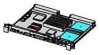
I/O Card Cage Replacement I/O Card Cage Replacement The I/O Card Cage is located at the rear left side of the rp24xx server. To replace the I/O Card Cage, follow the steps listed below: CAUTION Ensure that the system is shut down and power removed from the server before attempting removal or replacement of a component. Step 1. Grasp the I/O Card Cage, tilt the front up, and slide it down and into the chassis. CAUTION To prevent damage to the I/O Backplane when removing or replacing the card cage, do not scrape it against the CPU heat sink as you move the card cage into or out of the chassis. Step 2. Grasp the flat lever handle on the right side of the Card Cage and pull it up and out of the way. Align the I/O Backplane card connector with the System Board receiver and push in firmly to seat it. Push the flat lever handle down flush with the top of the Card Cage. Step 3. Secure the two captive Phillips-head screws located at the front of the Card Cage. Step 4. Replace the I/O card attached to the right side of the I/O Card Cage (slot 1) on the I/O Backplane as follows: a. Seat the I/O Card into its slot on the I/O Backplane. b. Replace the screw that attaches the I/O card to the rear bulkhead. NOTE A short-shaft or right-angle Phillips-head screwdriver must be used to replace the screw due to the short distance between the screw head and the right side of the chassis. c. If the card in slot 1 is a Secure Web Console card, plug the 5V power connector into the receptacle on the Guardian Service Protector card. The following photograph shows an empty I/O Card Cage. The following graphic shows the components of an I/O Card Cage. Chapter 249
-
 1
1 -
2
-
3
-
4
-
5
-
6
-
7
-
8
-
9
-
10
-
11
-
12
-
13
-
14
-
15
-
16
-
17
-
18
-
19
-
20
-
21
-
22
-
23
-
24
-
25
-
26
-
27
-
28
-
29
-
30
-
31
-
32
-
33
-
34
-
35
-
36
-
37
-
38
-
39
-
40
-
41
-
42
-
43
-
44
-
45
-
46
-
47
-
48
-
49
-
50
-
51
-
52
-
53
-
54
-
55
-
56
-
57
-
58
-
59
-
60
-
61
-
62
-
63
-
64
-
65
-
66
-
67
-
68
-
69
-
70
-
71
-
72
-
73
-
74
-
75
-
76
-
77
-
78
-
79
-
80
-
81
-
82
-
83
-
84
-
85
-
86
-
87
-
88
-
89
-
90
-
91
-
92
-
93
-
94
-
95
-
96
-
97
-
98
-
99
-
100
-
101
-
102
-
103
-
104
-
105
-
106
-
107
-
108
-
109
-
110
-
111
-
112
-
113
-
114
-
115
-
116
-
117
-
118
-
119
-
120
-
121
-
122
-
123
-
124
-
125
-
126
-
127
-
128
-
129
-
130
-
131
-
132
-
133
-
134
-
135
-
136
-
137
-
138
-
139
-
140
-
141
-
142
-
143
-
144
-
145
-
146
-
147
-
148
-
149
-
150
-
151
-
152
-
153
-
154
-
155
-
156
-
157
-
158
-
159
-
160
-
161
-
162
-
163
-
164
-
165
-
166
-
167
-
168
-
169
-
170
-
171
-
 172
172 -
 173
173 -
 174
174 -
 175
175 -
 176
176 -
 177
177 -
 178
178 -
 179
179 -
 180
180 -
 181
181 -
 182
182 -
183
-
184
-
185
-
186
-
187
-
188
-
189
-
190
-
191
-
192
-
193
-
194
-
195
-
196
-
197
-
198
-
199
-
200
-
201
-
202
 |
 |
