HP A4500A Hardware Manual - rp24xx, Customer Viewable - Page 72
Connect a System Console, Connect the Core Local Area Network (LAN), Connect Power Cords
 |
View all HP A4500A manuals
Add to My Manuals
Save this manual to your list of manuals |
Page 72 highlights
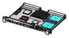
Server External Connections Ensure that all devices on the SCSI bus have a unique address and the last device is terminated. Refer to the documentation accompanying each device to learn how to set addresses and where to place terminators. Connect a System Console • Using the ASCII Terminal as a System Console. If an ASCII terminal is to be used as a console/UPS port, make sure that the keyboard is connected and a power cable is available. • Using a SecureWeb Console PCI card as a System Console. If the Secure Web Console PCI card is to be used as a system console, connect an RJ45 LAN cable to the Secure Web Console PCI card installed in an I/O card slot on the back of the server. NOTE The Web Console has a default Internet Protocol (IP) address of 192.0.0.192. Make sure that no other device, including other rp24xx servers, has this address before connecting the server to your LAN. • Using the LAN Console as a System Console. If a LAN Console is to be used as a system console, connect it to the system with an RJ45 LAN cable to the RJ45 connector labeled, 10BASE-T LAN Console connection on the back of the server. Connect the Core Local Area Network (LAN) Connect the 10/100BASE-T Core LAN on the system board to the LAN with an RJ45 LAN cable. Connect the RJ45 LAN cable to the server by attaching it to the RJ45 connector labeled, 10/100 Base-T Path: 0/0/0/0. Connect Power Cords Connect the power cord that is provided with the system to the server. For stand-alone servers, the power cord will be localized to each country's power application. If an HP Uninterruptible Power Supply (UPS) is the power source, use the power cord provided with the UPS. Connect power cords to all external devices at this time with the either the localized power cord, cabinet Power Distribution Unit (PDU) power cord, or the UPS power cord. For cabinet-mounted servers, the server power cord connects to the PDU in the cabinet. 80 Chapter
-
 1
1 -
2
-
3
-
4
-
5
-
6
-
7
-
8
-
9
-
10
-
11
-
12
-
13
-
14
-
15
-
16
-
17
-
18
-
19
-
20
-
21
-
22
-
23
-
24
-
25
-
26
-
27
-
28
-
29
-
30
-
31
-
32
-
33
-
34
-
35
-
36
-
37
-
38
-
39
-
40
-
41
-
42
-
43
-
44
-
45
-
46
-
47
-
48
-
49
-
50
-
51
-
52
-
53
-
54
-
55
-
56
-
57
-
58
-
59
-
60
-
61
-
62
-
63
-
64
-
65
-
66
-
 67
67 -
 68
68 -
 69
69 -
 70
70 -
 71
71 -
 72
72 -
 73
73 -
 74
74 -
 75
75 -
 76
76 -
 77
77 -
78
-
79
-
80
-
81
-
82
-
83
-
84
-
85
-
86
-
87
-
88
-
89
-
90
-
91
-
92
-
93
-
94
-
95
-
96
-
97
-
98
-
99
-
100
-
101
-
102
-
103
-
104
-
105
-
106
-
107
-
108
-
109
-
110
-
111
-
112
-
113
-
114
-
115
-
116
-
117
-
118
-
119
-
120
-
121
-
122
-
123
-
124
-
125
-
126
-
127
-
128
-
129
-
130
-
131
-
132
-
133
-
134
-
135
-
136
-
137
-
138
-
139
-
140
-
141
-
142
-
143
-
144
-
145
-
146
-
147
-
148
-
149
-
150
-
151
-
152
-
153
-
154
-
155
-
156
-
157
-
158
-
159
-
160
-
161
-
162
-
163
-
164
-
165
-
166
-
167
-
168
-
169
-
170
-
171
-
172
-
173
-
174
-
175
-
176
-
177
-
178
-
179
-
180
-
181
-
182
-
183
-
184
-
185
-
186
-
187
-
188
-
189
-
190
-
191
-
192
-
193
-
194
-
195
-
196
-
197
-
198
-
199
-
200
-
201
-
202
 |
 |
