HP A4500A Hardware Manual - rp24xx, Customer Viewable - Page 74
Installing Bezel End Caps, personal injury or death and can damage equipment.
 |
View all HP A4500A manuals
Add to My Manuals
Save this manual to your list of manuals |
Page 74 highlights
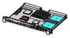
Installing a Stand-alone Server in a Cabinet WARNING If anti-tip stabilizers or ballast are not installed or are improperly installed on the cabinet, it can tip. Failure to follow this precaution can cause personal injury or death and can damage equipment. Step 2. Remove the stand alone server from it's packing materials, if not already unpacked. Step 3. Refer to the A-400/A-500 Server Slide Rail Installation instructions, for both server and cabinet rail installation instructions. Installing Bezel End Caps Each server is shipped with two metal brackets and two plastic end caps that are designed to be attached to a stand alone server if it is to be mounted in a cabinet. Locate these items and have them available for installation. The following diagram shows the location of bezel end caps and brackets on a racked server. 3 2 1 ccrr001 1 2 3 Callout # Item 1 Server-to-cabinet attachment screws 82 Chapter
-
 1
1 -
2
-
3
-
4
-
5
-
6
-
7
-
8
-
9
-
10
-
11
-
12
-
13
-
14
-
15
-
16
-
17
-
18
-
19
-
20
-
21
-
22
-
23
-
24
-
25
-
26
-
27
-
28
-
29
-
30
-
31
-
32
-
33
-
34
-
35
-
36
-
37
-
38
-
39
-
40
-
41
-
42
-
43
-
44
-
45
-
46
-
47
-
48
-
49
-
50
-
51
-
52
-
53
-
54
-
55
-
56
-
57
-
58
-
59
-
60
-
61
-
62
-
63
-
64
-
65
-
66
-
67
-
68
-
 69
69 -
 70
70 -
 71
71 -
 72
72 -
 73
73 -
 74
74 -
 75
75 -
 76
76 -
 77
77 -
 78
78 -
 79
79 -
80
-
81
-
82
-
83
-
84
-
85
-
86
-
87
-
88
-
89
-
90
-
91
-
92
-
93
-
94
-
95
-
96
-
97
-
98
-
99
-
100
-
101
-
102
-
103
-
104
-
105
-
106
-
107
-
108
-
109
-
110
-
111
-
112
-
113
-
114
-
115
-
116
-
117
-
118
-
119
-
120
-
121
-
122
-
123
-
124
-
125
-
126
-
127
-
128
-
129
-
130
-
131
-
132
-
133
-
134
-
135
-
136
-
137
-
138
-
139
-
140
-
141
-
142
-
143
-
144
-
145
-
146
-
147
-
148
-
149
-
150
-
151
-
152
-
153
-
154
-
155
-
156
-
157
-
158
-
159
-
160
-
161
-
162
-
163
-
164
-
165
-
166
-
167
-
168
-
169
-
170
-
171
-
172
-
173
-
174
-
175
-
176
-
177
-
178
-
179
-
180
-
181
-
182
-
183
-
184
-
185
-
186
-
187
-
188
-
189
-
190
-
191
-
192
-
193
-
194
-
195
-
196
-
197
-
198
-
199
-
200
-
201
-
202
 |
 |
