HP A4500A Hardware Manual - rp24xx, Customer Viewable - Page 68
Attaching the Pedestal Base, damage to the server.
 |
View all HP A4500A manuals
Add to My Manuals
Save this manual to your list of manuals |
Page 68 highlights
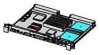
Unpack the Server Carefully lift the server out of the carton, unwrap it, set it on the work surface. WARNING Do not lift or carry the server by the bezel. The bezel is made of plastic and is attached to the server chassis by two bezel retainers and four ball-posts. It will only support the weight of the server chassis in an emergency. Failure to heed this warning may result in personal injury and/or permanent damage to the server. Attaching the Pedestal Base The pedestal base and two accompanying screws included with each stand alone server provides the option of standing the server on its side in order to conserve table space, or standing the server on the floor. To install the pedestal base, follow the instructions listed below: Step 1. As you are facing the front of the server, carefully stand it on its side with the right side up. Step 2. Place the pedestal, smooth side down, on the server side and align it lengthwise so that it is parallel with the server. Step 3. Center the pedestal front to rear and align the two recessed oblong holes with the corresponding two holes on the server's side. Step 4. Insert the two accompanying screws through the bottom of the pedestal and fasten securely to the server. Step 5. Stand the server on the pedestal. The following graphic illustrates the pedestal and server. NOTE The bezel and cover can remain on the server when attaching the pedestal base. 76 ccrr019 Chapter
-
 1
1 -
2
-
3
-
4
-
5
-
6
-
7
-
8
-
9
-
10
-
11
-
12
-
13
-
14
-
15
-
16
-
17
-
18
-
19
-
20
-
21
-
22
-
23
-
24
-
25
-
26
-
27
-
28
-
29
-
30
-
31
-
32
-
33
-
34
-
35
-
36
-
37
-
38
-
39
-
40
-
41
-
42
-
43
-
44
-
45
-
46
-
47
-
48
-
49
-
50
-
51
-
52
-
53
-
54
-
55
-
56
-
57
-
58
-
59
-
60
-
61
-
62
-
 63
63 -
 64
64 -
 65
65 -
 66
66 -
 67
67 -
 68
68 -
 69
69 -
 70
70 -
 71
71 -
 72
72 -
 73
73 -
74
-
75
-
76
-
77
-
78
-
79
-
80
-
81
-
82
-
83
-
84
-
85
-
86
-
87
-
88
-
89
-
90
-
91
-
92
-
93
-
94
-
95
-
96
-
97
-
98
-
99
-
100
-
101
-
102
-
103
-
104
-
105
-
106
-
107
-
108
-
109
-
110
-
111
-
112
-
113
-
114
-
115
-
116
-
117
-
118
-
119
-
120
-
121
-
122
-
123
-
124
-
125
-
126
-
127
-
128
-
129
-
130
-
131
-
132
-
133
-
134
-
135
-
136
-
137
-
138
-
139
-
140
-
141
-
142
-
143
-
144
-
145
-
146
-
147
-
148
-
149
-
150
-
151
-
152
-
153
-
154
-
155
-
156
-
157
-
158
-
159
-
160
-
161
-
162
-
163
-
164
-
165
-
166
-
167
-
168
-
169
-
170
-
171
-
172
-
173
-
174
-
175
-
176
-
177
-
178
-
179
-
180
-
181
-
182
-
183
-
184
-
185
-
186
-
187
-
188
-
189
-
190
-
191
-
192
-
193
-
194
-
195
-
196
-
197
-
198
-
199
-
200
-
201
-
202
 |
 |
