HP StorageWorks 16-EL SAN Switch 2/16 version 3.1.x - Installation Guide - Page 19
Hardware, intake and pushed out through the vents in the front panel. The fans provide
 |
View all HP StorageWorks 16-EL manuals
Add to My Manuals
Save this manual to your list of manuals |
Page 19 highlights
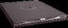
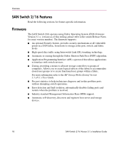
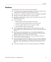
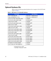
Overview Hardware The SAN Switch 2/16 consists of the following components: ■ A 1-Unit (U) chassis, designed for mounting in a 19-inch rack, with forced-air cooling that flows from the back of the switch to the front. ■ 16 optical ports, compatible with Small Form Factor Pluggable media (SFPs). ■ One RS-232 Serial port (DB9 connector) on the front panel. ■ One IEEE compliant RJ-45 connector on the front panel for use with 10/100 Mbps Ethernet or in-band. ■ A total of 36 LEDs: - One Power Switch LED on the left of the front panel - One Port Status and Port Speed LED for each of the 16 ports - One Power Supply LED on the back of the power supply - One Port Readiness LED on the back panel ■ Universal input power supplies with AC switches and built-in fans. (The power supplies plug into internal blind-mate connectors when installed in the chassis.) ■ Two fan trays, each containing two fans. Air is pulled in through the rear intake and pushed out through the vents in the front panel. The fans provide adequate cooling for the maximum switch power rating. ■ Three digital thermometers, capable of sensing a temperature range from -55°C to +125°C, in 0.5°C increments ■ A field-replaceable motherboard completely enclosed in an Electro-Magnetic Interference (EMI) enclosure tray, with logic and chassis ground connected to the chassis, and an embedded processor that processes frames up to 1,024 bytes. ■ A real-time clock (RTC) with a 10-year battery and 56 bytes of NVRAM. SAN Switch 2/16 Version 3.1.x Installation Guide 19
-
 1
1 -
2
-
3
-
4
-
5
-
6
-
7
-
8
-
9
-
10
-
11
-
12
-
13
-
 14
14 -
 15
15 -
 16
16 -
 17
17 -
 18
18 -
 19
19 -
 20
20 -
 21
21 -
 22
22 -
 23
23 -
 24
24 -
25
-
26
-
27
-
28
-
29
-
30
-
31
-
32
-
33
-
34
-
35
-
36
-
37
-
38
-
39
-
40
-
41
-
42
-
43
-
44
-
45
-
46
-
47
-
48
-
49
-
50
-
51
-
52
-
53
-
54
-
55
-
56
-
57
-
58
-
59
-
60
-
61
-
62
-
63
-
64
-
65
-
66
-
67
-
68
-
69
-
70
-
71
-
72
-
73
-
74
-
75
-
76
-
77
-
78
-
79
-
80
-
81
-
82
-
83
-
84
-
85
-
86
-
87
-
88
-
89
-
90
-
91
-
92
-
93
-
94
-
95
-
96
-
97
-
98
-
99
-
100
-
101
-
102
-
103
-
104
-
105
-
106
-
107
-
108
-
109
-
110
-
111
-
112
-
113
-
114
-
115
-
116
-
117
-
118
-
119
-
120
 |
 |