HP StorageWorks 16-EL SAN Switch 2/16 version 3.1.x - Installation Guide - Page 36
or EIA Rack., Position one of the outer slide rails in the rack, as described below
 |
View all HP StorageWorks 16-EL manuals
Add to My Manuals
Save this manual to your list of manuals |
Page 36 highlights
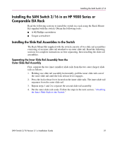
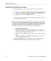
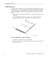
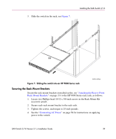
Installing the SAN Switch 2/16 Note: Before starting this procedure, verify that two of the slide mount L-brackets are preinstalled at the end of each outer slide rail. The L-brackets are necessary to attach the outer rails to the HP 9000 Series Rack. 1. Determine the appropriate placement for the switch inside the HP 9000 Series or EIA Rack. Note: The HP 9000 Series rack's rails are divided into Units (Us). Each U is marked with a small, round hole and three square openings for mounting equipment. 2. Locate the small, round marker hole on the HP 9000 Series rack's rails, which coincides with the location selected in step 1. Each marker hole delineates the beginning of one U. Note: The SAN Switch 2/16 requires one Unit of rack space. 3. Insert one square alignment washer on each of the eight 10-32 x 3/8-inch Phillips head screws. Note: The square alignment washers are mandatory for proper switch alignment. 4. Adjust the outer slide rail's length to fit the length of the HP 9000 Series Rack. 5. Position one of the outer slide rails in the rack, as described below: a. To allow the switch's port end to slide out the back of the rack, orient with the closed end of the outer slide rail towards the front of the rack. b. To allow the power supply end to slide out the front of the rack, orient the closed end of the outer slide rail towards the back of the rack. 6. Holding the outer slide rail in place, insert one 3-hole bar nut between the rack's rail and the L-bracket at the end of the outer slide rail, see Figure 6. 36 SAN Switch 2/16 Version 3.1.x Installation Guide
-
 1
1 -
2
-
3
-
4
-
5
-
6
-
7
-
8
-
9
-
10
-
11
-
12
-
13
-
14
-
15
-
16
-
17
-
18
-
19
-
20
-
21
-
22
-
23
-
24
-
25
-
26
-
27
-
28
-
29
-
30
-
 31
31 -
 32
32 -
 33
33 -
 34
34 -
 35
35 -
 36
36 -
 37
37 -
 38
38 -
 39
39 -
 40
40 -
 41
41 -
42
-
43
-
44
-
45
-
46
-
47
-
48
-
49
-
50
-
51
-
52
-
53
-
54
-
55
-
56
-
57
-
58
-
59
-
60
-
61
-
62
-
63
-
64
-
65
-
66
-
67
-
68
-
69
-
70
-
71
-
72
-
73
-
74
-
75
-
76
-
77
-
78
-
79
-
80
-
81
-
82
-
83
-
84
-
85
-
86
-
87
-
88
-
89
-
90
-
91
-
92
-
93
-
94
-
95
-
96
-
97
-
98
-
99
-
100
-
101
-
102
-
103
-
104
-
105
-
106
-
107
-
108
-
109
-
110
-
111
-
112
-
113
-
114
-
115
-
116
-
117
-
118
-
119
-
120
 |
 |