HP StorageWorks 16-EL SAN Switch 2/16 version 3.1.x - Installation Guide - Page 32
Attaching the Inner Slide Rails to the Switch, HP recommended method
 |
View all HP StorageWorks 16-EL manuals
Add to My Manuals
Save this manual to your list of manuals |
Page 32 highlights
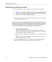
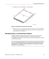
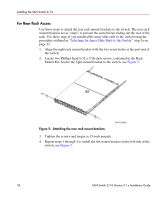
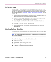
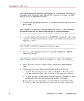
Installing the SAN Switch 2/16 Attaching the Inner Slide Rails to the Switch Use the following steps to secure each inner slide rail to the switch chassis. Caution: It is important to install the inner slide rails using the Phillips head, 8-32 x 3/16-inch screws supplied in the Rack Mount Kit. Installing screws longer than 3/16-inch can damage the switch. 1. Position the inner slide rails with the flat side against the switch, oriented in one of the following two ways: Note: HP recommends installing the SAN Switch 2/16 so that the port side of the switch slides out the rear of the HP 9000 Series Rack (as described in step 1a below). In this way, the switch faces the aisle where exhaust air is released. Air intake and exhaust for all components in the rack should flow in the same direction. a. HP recommended method: To allow the port side of the switch to slide out the rear of the rack: Orient the inner slide rail with the end containing the lock release lever towards the power supply end of the switch. b. To allow the power supply side of the switch to slide out the front of the rack: Orient the inner slide rail with the end containing the lock release lever towards the port end of the switch. 2. Locate three Phillips head, 8-32 x 3/16-inch screws provided in the Rack Mount Kit. Secure the inner slide rail to the switch, see Figure 4. 32 SAN Switch 2/16 Version 3.1.x Installation Guide
-
 1
1 -
2
-
3
-
4
-
5
-
6
-
7
-
8
-
9
-
10
-
11
-
12
-
13
-
14
-
15
-
16
-
17
-
18
-
19
-
20
-
21
-
22
-
23
-
24
-
25
-
26
-
 27
27 -
 28
28 -
 29
29 -
 30
30 -
 31
31 -
 32
32 -
 33
33 -
 34
34 -
 35
35 -
 36
36 -
 37
37 -
38
-
39
-
40
-
41
-
42
-
43
-
44
-
45
-
46
-
47
-
48
-
49
-
50
-
51
-
52
-
53
-
54
-
55
-
56
-
57
-
58
-
59
-
60
-
61
-
62
-
63
-
64
-
65
-
66
-
67
-
68
-
69
-
70
-
71
-
72
-
73
-
74
-
75
-
76
-
77
-
78
-
79
-
80
-
81
-
82
-
83
-
84
-
85
-
86
-
87
-
88
-
89
-
90
-
91
-
92
-
93
-
94
-
95
-
96
-
97
-
98
-
99
-
100
-
101
-
102
-
103
-
104
-
105
-
106
-
107
-
108
-
109
-
110
-
111
-
112
-
113
-
114
-
115
-
116
-
117
-
118
-
119
-
120
 |
 |