HP StorageWorks 16-EL SAN Switch 2/16 version 3.1.x - Installation Guide - Page 43
Installing the rubber washers
 |
View all HP StorageWorks 16-EL manuals
Add to My Manuals
Save this manual to your list of manuals |
Page 43 highlights
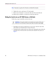
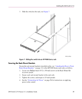
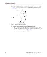
Installing the SAN Switch 2/16 I [1] Select this graphic frame. [2] Select File. [3] Select Import. [4] Select File. [5] Choose the appropriate graphic file name. [6] Make sure you've checked the Copy Into Document. [7] Select Import. Position the illustration as required. [8] Adjust the size of the outer graphic frame as required. Delete this set of instructions 1 2 1 Rubber washer (1 of 2) 2 Rear rail tray bracket (1 of 2) Figure 10: Installing the rubber washers SHR-2559A b. Insert the alignment pins attached to the outer rail front flange into the center opening in the rack. 6. Install one M5 Torx screw in the upper hole location of the right rail. Then, install one M5 Torx screw in the lower location of the left rail. See Figure 11. Note: Do not install the upper left and the lower right screws until later. SAN Switch 2/16 Version 3.1.x Installation Guide 43
-
 1
1 -
2
-
3
-
4
-
5
-
6
-
7
-
8
-
9
-
10
-
11
-
12
-
13
-
14
-
15
-
16
-
17
-
18
-
19
-
20
-
21
-
22
-
23
-
24
-
25
-
26
-
27
-
28
-
29
-
30
-
31
-
32
-
33
-
34
-
35
-
36
-
37
-
 38
38 -
 39
39 -
 40
40 -
 41
41 -
 42
42 -
 43
43 -
 44
44 -
 45
45 -
 46
46 -
 47
47 -
 48
48 -
49
-
50
-
51
-
52
-
53
-
54
-
55
-
56
-
57
-
58
-
59
-
60
-
61
-
62
-
63
-
64
-
65
-
66
-
67
-
68
-
69
-
70
-
71
-
72
-
73
-
74
-
75
-
76
-
77
-
78
-
79
-
80
-
81
-
82
-
83
-
84
-
85
-
86
-
87
-
88
-
89
-
90
-
91
-
92
-
93
-
94
-
95
-
96
-
97
-
98
-
99
-
100
-
101
-
102
-
103
-
104
-
105
-
106
-
107
-
108
-
109
-
110
-
111
-
112
-
113
-
114
-
115
-
116
-
117
-
118
-
119
-
120
 |
 |
