HP StorageWorks 16-EL SAN Switch 2/16 version 3.1.x - Installation Guide - Page 27
Installation Guidelines, Selecting an Operating Location
 |
View all HP StorageWorks 16-EL manuals
Add to My Manuals
Save this manual to your list of manuals |
Page 27 highlights
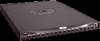
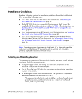
Installing the SAN Switch 2/16 Installation Guidelines Read the following sections for installation guidelines. Install the SAN Switch 2/16 in one of the following ways: ■ As a stand-alone unit on a flat surface. For instructions, see Installing the SAN Switch as a Stand-alone Unit, page 30. ■ In the HP 9000 Series (or comparable) Rack using the Rack Mount Kit supplied with the switch, contents as outlined in Table 3. For instructions, see Installing the SAN Switch 2/16 in an HP 9000 Series or Comparable EIA Rack, page 31. ■ As a fixed component in an HP System/e rack. For instructions, see Installing the Switch in the Optional HP System/e Rack, page 40. ■ As a fixed component using the optional HP StorageWorks SAN Switch Universal Rack Mount Kit. For instructions, see Installing the Switch Using the HP StorageWorks SAN Switch Universal Rack Mount Kit on page page 46. Note: Depending on time of purchase, the SAN Switch 2/16 ships with one of the rack mount kits listed above. HP reserves the right to substitute rack mount kits, providing applicable instructions with each switch. Selecting an Operating Location To ensure correct operation of the switch, the location where the switch is in use must meet the following requirements: ■ Adequate supply circuit, line fusing, and wire size, as specified by the electrical rating on the switch nameplate. ■ An air flow of at least 300 cubic feet per minute, available in the immediate vicinity of the switch. ■ If installing the switch in the HP 9000 Series, HP System/e or comparable Electronics Industries Association (EIA) rack: - All equipment installed in the rack should have a reliable branch circuit ground connection, and should not rely on a connection to a branch circuit, such as a power strip. SAN Switch 2/16 Version 3.1.x Installation Guide 27
-
 1
1 -
2
-
3
-
4
-
5
-
6
-
7
-
8
-
9
-
10
-
11
-
12
-
13
-
14
-
15
-
16
-
17
-
18
-
19
-
20
-
21
-
 22
22 -
 23
23 -
 24
24 -
 25
25 -
 26
26 -
 27
27 -
 28
28 -
 29
29 -
 30
30 -
 31
31 -
 32
32 -
33
-
34
-
35
-
36
-
37
-
38
-
39
-
40
-
41
-
42
-
43
-
44
-
45
-
46
-
47
-
48
-
49
-
50
-
51
-
52
-
53
-
54
-
55
-
56
-
57
-
58
-
59
-
60
-
61
-
62
-
63
-
64
-
65
-
66
-
67
-
68
-
69
-
70
-
71
-
72
-
73
-
74
-
75
-
76
-
77
-
78
-
79
-
80
-
81
-
82
-
83
-
84
-
85
-
86
-
87
-
88
-
89
-
90
-
91
-
92
-
93
-
94
-
95
-
96
-
97
-
98
-
99
-
100
-
101
-
102
-
103
-
104
-
105
-
106
-
107
-
108
-
109
-
110
-
111
-
112
-
113
-
114
-
115
-
116
-
117
-
118
-
119
-
120
 |
 |