HP StorageWorks 8/80 HP StorageWorks 8Gb SAN Switch hardware reference manual - Page 27
Installation and safety considerations, Electrical considerations, Environmental considerations
 |
View all HP StorageWorks 8/80 manuals
Add to My Manuals
Save this manual to your list of manuals |
Page 27 highlights
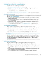
Installation and safety considerations Install the switch using one of the following methods: • As a stand-alone unit on a flat surface. See "Installing the switch as a stand-alone device" on page 29. • HP highly recommends mounting the switch in one of the following HP customized racks • HP System/e Rack • HP 10000 G2 Series Rack and HP 10000 Series Rack See "Installing the switch using the SAN Switch Rack Mount Kit" on page 30 for detailed instructions. Electrical considerations For successful installation and operation of the switch, ensure that the following electrical requirements are met. See Power supply specifications. • The primary outlet is correctly wired, protected by a circuit breaker, and grounded in accordance with local electrical codes. • The supply circuit, line fusing, and wire size are adequate, as specified by the electrical rating on the switch nameplate. • A minimum of 79.8 cubic meters/hour (47 cubic feet/minute) of air flow is available to the air intake vents on the nonport side of the switch. • The power supply standards provided in "Power supply specifications" on page 65, are met. Environmental considerations Before installing the switch, verify that the following environmental requirements are met: • Install the switch with the nonport side, which contains the air intake vents, facing the cool-air aisle. • All equipment in the rack forces air in the same direction, to avoid taking in exhaust air. • A minimum of 24 cubic ft/min of air flow is available to the air intake vents on the nonport side of the switch. • The ambient air temperature does not exceed 40° C (104° F) while the switch is operating. IMPORTANT: The 40ºC value applies to the ambient air temperature at the air intake vents on the nonport side of the switch. The temperature inside the switch can be up to 80ºC (176 ºF) during switch operation. If the internal temperature range exceeds the operating ranges of the components, the LEDs, error messages, and Fabric Watch alerts indicate a problem. Enter the tempshow or Fabric Watch command to view the temperature status. Rack mount considerations If you are installing the switch in a rack, verify that the following requirements are met: • The cabinet or rack must be a standard Electronic Industries Association (EIA) cabinet. • Plan rack mount space that is 1 rack unit (4.45 cm; 1.75 in) high, 48.3 cm (19 in.) wide. • Ground all equipment in the cabinet through a reliable branch circuit connection, and maintain ground at all times. Do not rely on a secondary connection to a branch circuit, such as a power strip. • Ensure that air flow and temperature requirements are met on an ongoing basis, particularly if the switch is installed in a closed or multirack assembly. • Verify that the additional weight of the switch does not exceed the cabinet's weight limits. 8Gb SAN Switch hardware reference manual 27
-
 1
1 -
2
-
3
-
4
-
5
-
6
-
7
-
8
-
9
-
10
-
11
-
12
-
13
-
14
-
15
-
16
-
17
-
18
-
19
-
20
-
21
-
 22
22 -
 23
23 -
 24
24 -
 25
25 -
 26
26 -
 27
27 -
 28
28 -
 29
29 -
 30
30 -
 31
31 -
 32
32 -
33
-
34
-
35
-
36
-
37
-
38
-
39
-
40
-
41
-
42
-
43
-
44
-
45
-
46
-
47
-
48
-
49
-
50
-
51
-
52
-
53
-
54
-
55
-
56
-
57
-
58
-
59
-
60
-
61
-
62
-
63
-
64
-
65
-
66
-
67
-
68
-
69
-
70
-
71
-
72
-
73
-
74
-
75
-
76
-
77
-
78
-
79
-
80
-
81
-
82
-
83
-
84
 |
 |