HP StorageWorks 8/80 HP StorageWorks 8Gb SAN Switch hardware reference manual - Page 35
Securing the inner rails to an MP Router, To attach the inner rails to the SAN Switch 2/16
 |
View all HP StorageWorks 8/80 manuals
Add to My Manuals
Save this manual to your list of manuals |
Page 35 highlights
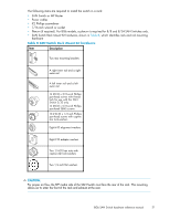
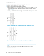
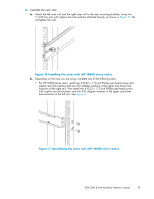
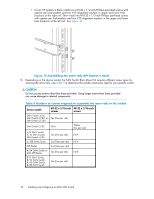
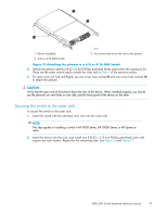
6. Identify the appropriate screw holes to install the inner rails to your specific device: a. To attach the inner rails to the SAN Switch 2/16, SAN Switch 2/8V, or SAN Switch 2/16V, use the screw holes marked 8. b. To attach the inner rails to the SAN Switch 2/32, use the screw holes marked 32. c. To attach the inner rails to the 4/8, 4/16, 8/8, or 8/24 SAN Switches, use the five screw holes marked 8. The plenum requires one screw hole marked 8 and one screw hole marked 16, as shown in Figure 15 on page 37. d. To attach the inner rails to the 4/32, 4/32B, 4/64, 8/40, 8/80 SAN Switch or 400 MP Router, use the screw holes marked 16, as shown in Figure 14 on page 36. e. To attach the inner rails to the MP Router, use the screw holes marked R. CAUTION: Remember to use the screw holes labelled 8 when attaching the inner rails to the SAN Switch 2/16V or SAN Switch 2/16N. 7. Secure the two inner rails (one on each side) to the device, using the appropriate number of screws (see Table 9): For example, Figure 13 shows an inner rail attached to the MP Router with three screws using the rail screw holes marked R. Attaching both rails require six screws. Also, Figure 14 shows an inner rail attached to the 4/64 SAN Switch with five screws using the rail screw holes marked 16. Attaching both rails require ten screws. PPOOWRETRS SYSTEM MGMT1 CONSOLE MGMT2 15 14 LINK 13 12 11 SFLICPNE/KGE/bADECT 10 ACTIVITY SPEED 9 8 7 6 5 4 3 2 100-240 VAC 6.0 A 47-63 Hz 1 0 DC OK AC OK 100-240 VAC 6.0 A 47-63 Hz DC OK AC OK MRO25007a Figure 13 Securing the inner rails to an MP Router 8Gb SAN Switch hardware reference manual 35
-
 1
1 -
2
-
3
-
4
-
5
-
6
-
7
-
8
-
9
-
10
-
11
-
12
-
13
-
14
-
15
-
16
-
17
-
18
-
19
-
20
-
21
-
22
-
23
-
24
-
25
-
26
-
27
-
28
-
29
-
 30
30 -
 31
31 -
 32
32 -
 33
33 -
 34
34 -
 35
35 -
 36
36 -
 37
37 -
 38
38 -
 39
39 -
 40
40 -
41
-
42
-
43
-
44
-
45
-
46
-
47
-
48
-
49
-
50
-
51
-
52
-
53
-
54
-
55
-
56
-
57
-
58
-
59
-
60
-
61
-
62
-
63
-
64
-
65
-
66
-
67
-
68
-
69
-
70
-
71
-
72
-
73
-
74
-
75
-
76
-
77
-
78
-
79
-
80
-
81
-
82
-
83
-
84
 |
 |