HP StorageWorks 8/80 HP StorageWorks 8Gb SAN Switch hardware reference manual - Page 57
fan assembly overview, SAN Switch fan assemblies on the nonport side
 |
View all HP StorageWorks 8/80 manuals
Add to My Manuals
Save this manual to your list of manuals |
Page 57 highlights
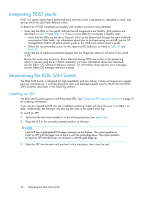
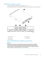
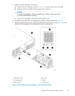
8/80 fan assembly overview The 8/80 SAN Switch integrates three fan assemblies (see Figure 25). Fabric OS identifies the fans from left to right as Fan assembly #3, Fan assembly #2, and Fan assembly #1. 1 Scale: 1/8" = 1" MmAoaTuxniTmtEinuNgmtoTscIbrOeewN5lme:nmgtohrfo13r /ra6c4kin. 5 4 2 3 Scale: 5/16" = 1" 26460a 1 8/80 SAN Switch 2 Nonport side 3 Fan assembly #3 4 Fan assembly #2 5. Fan assembly #1 Figure 25 8/80 SAN Switch fan assemblies on the nonport side CAUTION: Disassembling any part of the fan assembly voids the part warranty and regulatory certifications. There are no user-serviceable parts inside the fan assembly. Because the cooling system relies on pressurized air, do not leave any of the fan assembly slots empty longer than two minutes while the switch is operating. If a fan assembly fails, leave it in the switch until it can be replaced. Maintain all three fan assemblies in operational condition to provide redundancy. 8Gb SAN Switch hardware reference manual 57
-
 1
1 -
2
-
3
-
4
-
5
-
6
-
7
-
8
-
9
-
10
-
11
-
12
-
13
-
14
-
15
-
16
-
17
-
18
-
19
-
20
-
21
-
22
-
23
-
24
-
25
-
26
-
27
-
28
-
29
-
30
-
31
-
32
-
33
-
34
-
35
-
36
-
37
-
38
-
39
-
40
-
41
-
42
-
43
-
44
-
45
-
46
-
47
-
48
-
49
-
50
-
51
-
 52
52 -
 53
53 -
 54
54 -
 55
55 -
 56
56 -
 57
57 -
 58
58 -
 59
59 -
 60
60 -
 61
61 -
 62
62 -
63
-
64
-
65
-
66
-
67
-
68
-
69
-
70
-
71
-
72
-
73
-
74
-
75
-
76
-
77
-
78
-
79
-
80
-
81
-
82
-
83
-
84
 |
 |
