HP StorageWorks 8/80 HP StorageWorks 8Gb SAN Switch hardware reference manual - Page 40
Power on the 8Gb SAN Switch, Make a serial connection, Connecting the serial cable
 |
View all HP StorageWorks 8/80 manuals
Add to My Manuals
Save this manual to your list of manuals |
Page 40 highlights
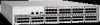
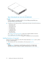
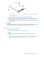
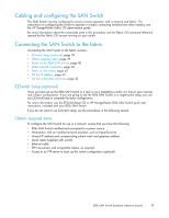
Power on the 8Gb SAN Switch The 8/8 and 8/24 SAN Switches use one power cord. The 8/40 and 8/80 SAN Switches use two power cords. To power on: IMPORTANT: The 8/8 and 8/24 SAN Switches do not have an on/off switch. Power is supplied as soon as you connect it to an AC power source. 1. Connect the power cord(s) to a power inlet on the switch and to a power source. Verify that the cord(s) use a minimum service loop of 6 inches, to avoid stress. IMPORTANT: To protect against AC failure on the 8/40 SAN Switch or the 8/80 SAN Switch, connect each power cord to outlets on separate circuits. 2. For the 8/40 and 8/80 SAN Switches, set the two AC switches to the ON position (1). Power is supplied to the switch as soon as the first power supply is connected and turned on. The power supply LEDs display amber until POST completes, and then change to green. The switch usually requires from 1 to 3 minutes to boot and complete POST. 3. After POST completes, verify that the switch Power and Status LEDs light are green. Make a serial connection All basic configuration tasks require a serial connection: 1. Connect the serial cable to an RS-232 serial port on the workstation, as shown in Figure 18. Figure 18 shows the 8/24 SAN Switch; however, this procedure is similar for all SAN Switches. NOTE: If the serial port on the workstation uses an RJ-45 connector instead of an RS-232 connector, remove the adapter on the end of the serial cable, and insert the exposed RJ-45 connector into the RJ-45 serial port on the workstation. HP StorageWorks 8/40 SAN Switch 0 41 2 5 3 6 7 8 12 9 13 10 14 11 15 16 20 17 21 18 22 19 23 24 28 25 29 26 30 27 31 32 36 33 37 34 38 35 39 AMmTaoxuTinmEtiunNmg tTsocIbrOeewN5mle:nmgtohr f1o3r/r6a4ckin. 26473a Figure 18 Connecting the serial cable 2. Close any serial communication programs running on the workstation. 40 Installing and configuring an 8Gb SAN Switch
-
 1
1 -
2
-
3
-
4
-
5
-
6
-
7
-
8
-
9
-
10
-
11
-
12
-
13
-
14
-
15
-
16
-
17
-
18
-
19
-
20
-
21
-
22
-
23
-
24
-
25
-
26
-
27
-
28
-
29
-
30
-
31
-
32
-
33
-
34
-
 35
35 -
 36
36 -
 37
37 -
 38
38 -
 39
39 -
 40
40 -
 41
41 -
 42
42 -
 43
43 -
 44
44 -
 45
45 -
46
-
47
-
48
-
49
-
50
-
51
-
52
-
53
-
54
-
55
-
56
-
57
-
58
-
59
-
60
-
61
-
62
-
63
-
64
-
65
-
66
-
67
-
68
-
69
-
70
-
71
-
72
-
73
-
74
-
75
-
76
-
77
-
78
-
79
-
80
-
81
-
82
-
83
-
84
 |
 |