HP Superdome SX2000 Installation Guide, Sixth Edition - HP Integrity Superdome - Page 20
Power Supply Mounting Screws Location, I/O Chassis Mounting Screws
 |
View all HP Superdome SX2000 manuals
Add to My Manuals
Save this manual to your list of manuals |
Page 20 highlights
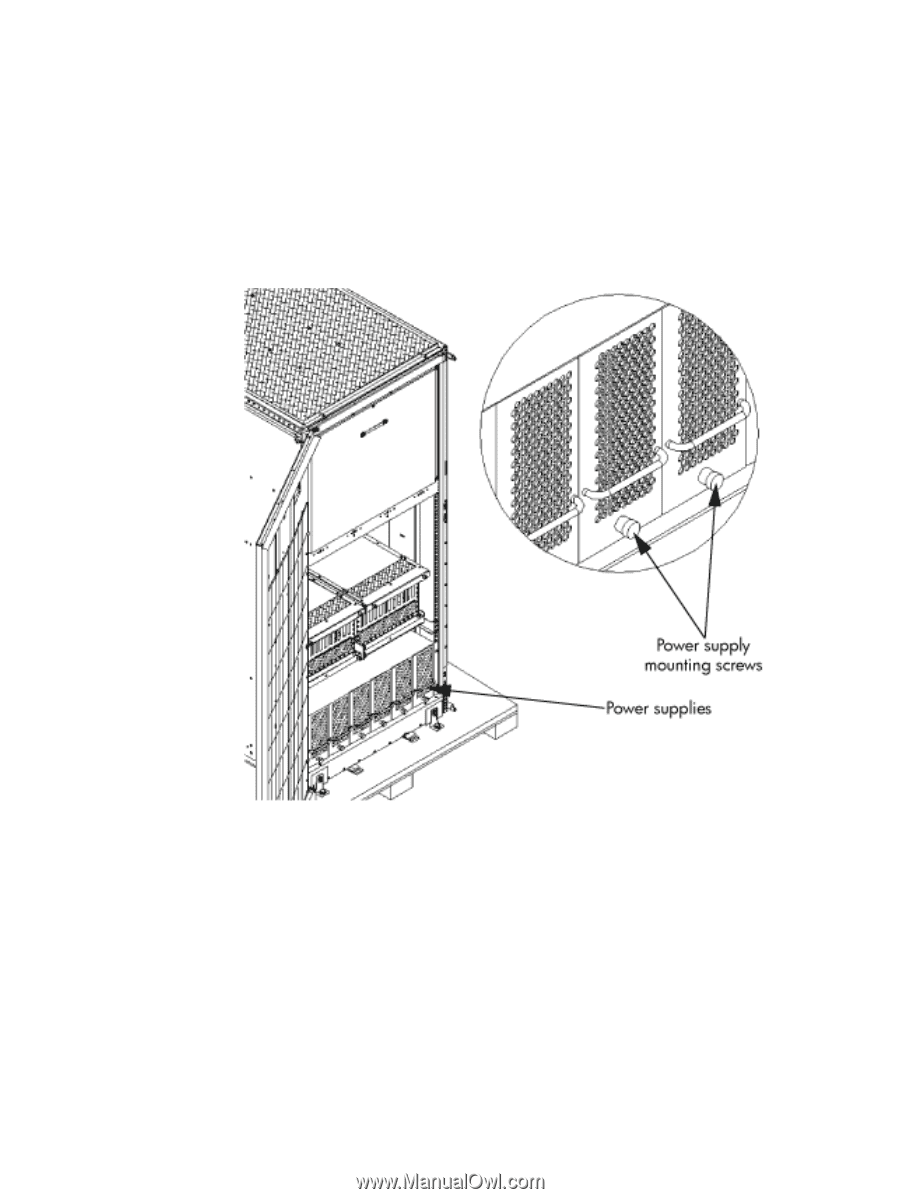
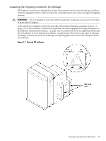
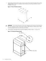
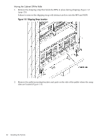
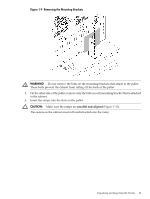
7. Remove the plastic antistatic bag by lifting it straight up off the cabinet. If the cabinet or any components are damaged, follow the claims procedure. Some damage can be repaired by replacing the damaged part. If you find extensive damage, you might need to repack and return the entire cabinet to HP. Inspecting the Cabinet To inspect the cabinet exterior for signs of shipping damage, follow these steps: 1. Look at the top and sides for dents, warping, or scratches. 2. Verify that the power supply mounting screws are in place and locked (Figure 1-6). Figure 1-6 Power Supply Mounting Screws Location 3. Verify that the I/O chassis mounting screws are in place and secure (Figure 1-7). Inspect all components for signs of shifting during shipment or any signs of damage. Figure 1-7 I/O Chassis Mounting Screws 20 Installing the System
-
 1
1 -
2
-
3
-
4
-
5
-
6
-
7
-
8
-
9
-
10
-
11
-
12
-
13
-
14
-
 15
15 -
 16
16 -
 17
17 -
 18
18 -
 19
19 -
 20
20 -
 21
21 -
 22
22 -
 23
23 -
 24
24 -
 25
25 -
26
-
27
-
28
-
29
-
30
-
31
-
32
-
33
-
34
-
35
-
36
-
37
-
38
-
39
-
40
-
41
-
42
-
43
-
44
-
45
-
46
-
47
-
48
-
49
-
50
-
51
-
52
-
53
-
54
-
55
-
56
-
57
-
58
-
59
-
60
-
61
-
62
-
63
-
64
-
65
-
66
-
67
-
68
 |
 |