HP Superdome SX2000 Installation Guide, Sixth Edition - HP Integrity Superdome - Page 41
CAUTION, Checking PDCA Test Points 5-Wire, Table 1-3 4- and 5-Wire Voltage Ranges
 |
View all HP Superdome SX2000 manuals
Add to My Manuals
Save this manual to your list of manuals |
Page 41 highlights
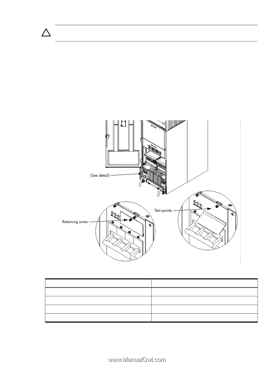
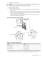
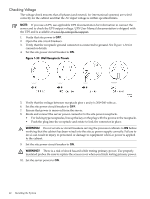
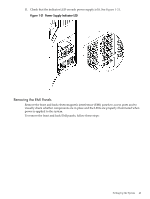
6. Reinstall the rear PDCA bezel. CAUTION: Do not measure voltages with the PDCA breaker set to ON. Make sure the electrical panel breaker is ON and the PDCA breaker is OFF. 7. Plug in the PDCA connector. 8. Check the voltage at the PDCA: a. Using a T-20 driver, remove the screw on the hinged panel at the top of the PDCA. (Figure 1-29). b. Using a voltmeter, measure the test points and compare the values to the ranges given in Table 1-3 (page 41) to make sure the voltages conform to the specifications for the PDCA and local electrical specifications. If the voltage values do not match the specifications, have the customer contact an electrician to troubleshoot the problem. Figure 1-29 Checking PDCA Test Points (5-Wire) Table 1-3 4- and 5-Wire Voltage Ranges 4-Wire 5-Wire L2 to L3: 200-240 V L1 to N: 200-240 V L2 to L1: 200-240 V L2 to N: 200-240 V L1 to L3: 200-240 V L3 to N: 200-240 V N to Ground: 1 1 Neutral to ground voltage can vary from millivolts to several volts depending on the distance to the ground/neutral bond at the transformer. Any voltage over 3 V must be investigated by a site preparation or power specialist. Setting Up the System 41
-
 1
1 -
2
-
3
-
4
-
5
-
6
-
7
-
8
-
9
-
10
-
11
-
12
-
13
-
14
-
15
-
16
-
17
-
18
-
19
-
20
-
21
-
22
-
23
-
24
-
25
-
26
-
27
-
28
-
29
-
30
-
31
-
32
-
33
-
34
-
35
-
 36
36 -
 37
37 -
 38
38 -
 39
39 -
 40
40 -
 41
41 -
 42
42 -
 43
43 -
 44
44 -
 45
45 -
 46
46 -
47
-
48
-
49
-
50
-
51
-
52
-
53
-
54
-
55
-
56
-
57
-
58
-
59
-
60
-
61
-
62
-
63
-
64
-
65
-
66
-
67
-
68
 |
 |