HP Visualize J5000 hp Visualize J5000, J7000 workstations parts removal and re - Page 10
Product Exploded Diagram
 |
View all HP Visualize J5000 manuals
Add to My Manuals
Save this manual to your list of manuals |
Page 10 highlights
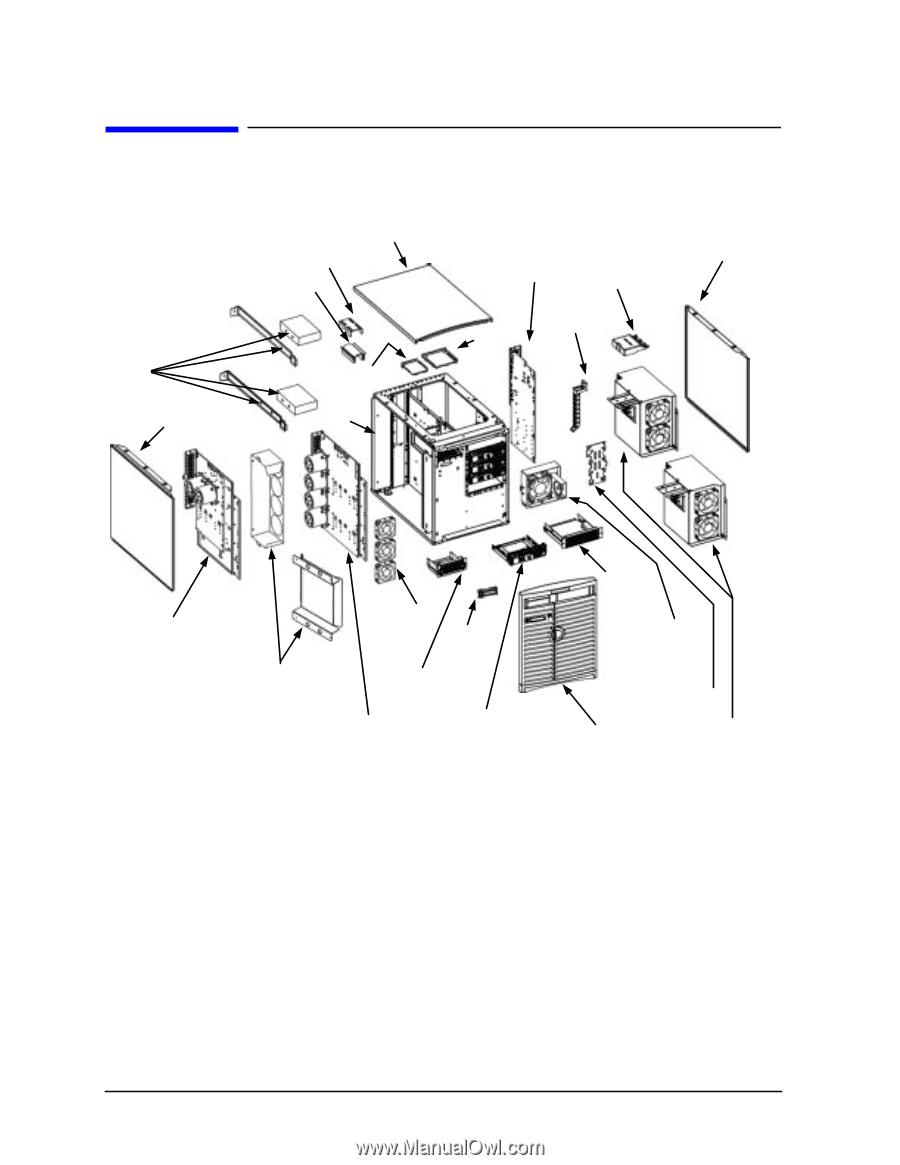
Getting Started Product Exploded Diagram Product Exploded Diagram Refer to the figure below for a basic parts overview of the J Class workstation. Top panel Flex cable retainer Flex cable DC/DC converter units and tie downs for J7000 Left side panel DDS-3/floppy EMI cover Chassis Right side panel I/O board Bus bar shield CD EMI cover PCI retainer clip J5000 system board tray assembly System board cooling fans Power switch/LCD Rear and front air dividers for J7000 DDS-3/floppy drive carrier J7000 system board tray assembly Hard disk drive carrier CD drive carrier I/O cooling fan and speaker SCA hard disk interface Front bezel Power supply for J7000 (top) and J5000 (bottom) 10 Chapter 1
-
 1
1 -
2
-
3
-
4
-
 5
5 -
 6
6 -
 7
7 -
 8
8 -
 9
9 -
 10
10 -
 11
11 -
 12
12 -
 13
13 -
 14
14 -
 15
15 -
16
-
17
-
18
-
19
-
20
-
21
-
22
-
23
-
24
-
25
-
26
-
27
-
28
-
29
-
30
-
31
-
32
-
33
-
34
-
35
-
36
-
37
-
38
-
39
-
40
-
41
-
42
-
43
-
44
-
45
-
46
-
47
-
48
-
49
-
50
-
51
-
52
-
53
-
54
-
55
-
56
 |
 |
10
Chapter 1
Getting Started
Product Exploded Diagram
Product Exploded Diagram
Refer to the figure below for a basic parts overview of the J Class workstation.
Power supply for
J7000 (top) and
J5000 (bottom)
Flex cable
Flex cable
retainer
Top panel
CD
EMI
cover
Front bezel
I/O board
PCI
retainer
clip
Bus bar shield
Right side panel
DC/DC converter
units and
tie downs
for J7000
Left side panel
Chassis
DDS-3/floppy
EMI cover
SCA hard
disk interface
CD drive
carrier
I/O cooling fan
and speaker
Hard disk
drive carrier
Power
switch/LCD
J5000 system board
tray assembly
DDS-3/floppy
drive carrier
Rear and
front air dividers
for J7000
J7000 system board
tray assembly
System board
cooling fans