HP Visualize J5000 hp Visualize J5000, J7000 workstations parts removal and re - Page 14
Removing the Top and Side Panels
 |
View all HP Visualize J5000 manuals
Add to My Manuals
Save this manual to your list of manuals |
Page 14 highlights
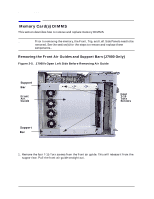
Parts Removal and Replacement Top, Front, and Side Panels Removing the Top and Side Panels 1. Facing the back of the workstation, remove the T-15 Torx thumbscrew located in each top corner of the back of the workstation. The upper left one (when facing the back of the workstation) is the power supply interlock-a safety feature that disengages the power supply when the thumbscrew is removed. Figure 2-3. Back View of the Workstation 2 Top Panel 3 Right Side Panel Left Side Panel 3 Hole for T-15 Torx Thumbscrew (Power Supply Interlock) 1 Hole for T-15 Torx Thumbscrew 2. Slide the top panel toward the back of the workstation and then lift up to remove it. Set the top panel and its screws aside. 3. Lift one of the side panels up and away from the chassis and out of its groove in the bottom of the side of the chassis. Remove the other side panel in the same way. Set the panels aside. CAUTION To avoid damage to internal components, leave the system in the upright position. 14 Chapter 2
-
 1
1 -
2
-
3
-
4
-
5
-
6
-
7
-
8
-
 9
9 -
 10
10 -
 11
11 -
 12
12 -
 13
13 -
 14
14 -
 15
15 -
 16
16 -
 17
17 -
 18
18 -
 19
19 -
20
-
21
-
22
-
23
-
24
-
25
-
26
-
27
-
28
-
29
-
30
-
31
-
32
-
33
-
34
-
35
-
36
-
37
-
38
-
39
-
40
-
41
-
42
-
43
-
44
-
45
-
46
-
47
-
48
-
49
-
50
-
51
-
52
-
53
-
54
-
55
-
56
 |
 |
