HP Visualize J5000 hp Visualize J5000, J7000 workstations parts removal and re - Page 21
Installing the Power Supply, Steps 1-2, Installing the Power Supply, Steps
 |
View all HP Visualize J5000 manuals
Add to My Manuals
Save this manual to your list of manuals |
Page 21 highlights
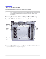
Figure 2-10. Installing the Power Supply, Steps 1-2 Parts Removal and Replacement Power Supply Step 1: Replace Jack Screws Step 2: Replace T-15 Torx Screws 2. Replace the two T-15 Torx screws in the back of the workstation and the one T-15 Torx screw in the lower left corner of the power supply (Step 2 above). Replace the T-15 Torx thumbscrews connecting the bus bars to the power supply. (Bus bar screws have washers and are longer than the other T-15 Torx screws.) Adjust the bus bars as necessary to prevent them from touching. The screws should be tightened firmly to insure contact (Step 3 below). CAUTION Verify that adjacent bus bars are not touching each other. Figure 2-11. Installing the Power Supply, Steps 3-5 Step 3: Replace Busbar Screws Step 4: Replace Busbar Shield Step 5: Replace PCI Retainer Clip Figure 2-12. Replace the bus bar shield (Step 4). 3. Replace the PCI retainer clip (Step 5). Chapter 2 21
-
 1
1 -
2
-
3
-
4
-
5
-
6
-
7
-
8
-
9
-
10
-
11
-
12
-
13
-
14
-
15
-
 16
16 -
 17
17 -
 18
18 -
 19
19 -
 20
20 -
 21
21 -
 22
22 -
 23
23 -
 24
24 -
 25
25 -
 26
26 -
27
-
28
-
29
-
30
-
31
-
32
-
33
-
34
-
35
-
36
-
37
-
38
-
39
-
40
-
41
-
42
-
43
-
44
-
45
-
46
-
47
-
48
-
49
-
50
-
51
-
52
-
53
-
54
-
55
-
56
 |
 |
