IBM 8668 Hardware Maintenance Manual - Page 64
Adapter installation, Start Options, Attention
 |
UPC - 087944723158
View all IBM 8668 manuals
Add to My Manuals
Save this manual to your list of manuals |
Page 64 highlights
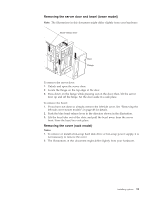
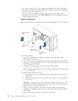
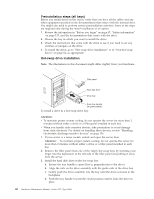
v The system scans PCI slot 1, the system board Ethernet, PCI slots 2 through 5, and then the system board SCSI channels A and B, if you have not changed the boot precedence from the default. You can use the Configuration/Setup Utility program to change the boot precedence for your server. Select Start Options from the Configuration/Setup Utility program main menu. Adapter installation Note: The illustrations in this document might differ slightly from your hardware. Adapter-retention bracket Expansion-slot cover Adapter Adapter support bracket retaining clip Adapter-support bracket To install an adapter: 1. Review the information in "Before you begin" on page 47 and "Safety information" on page 133. 2. Turn off the server and peripheral devices and disconnect all external cables and power cords; then, remove the cover. See "Removing the cover, door, and bezel" on page 48 for details. 3. Determine which expansion slot you will use for the adapter. Note: Check the instructions that come with the adapter for any requirements or restrictions. 4. Remove the expansion-slot cover: a. Press the arrow on the adapter-retention bracket release tab and remove the bracket. b. Slide the expansion-slot cover out of the server. Store it in a safe place for future use. Attention: Expansion-slot covers must be installed in all vacant slots. This maintains the electronic emissions characteristics of the system and ensures proper cooling of system components. 5. Refer to the documentation that comes with the adapter for any cabling instructions. It might be easier for you to route any cables before you install the adapter. 6. Remove the adapter from the static-protective package. 56 Hardware Maintenance Manual: xSeries 232, Type 8668
-
 1
1 -
2
-
3
-
4
-
5
-
6
-
7
-
8
-
9
-
10
-
11
-
12
-
13
-
14
-
15
-
16
-
17
-
18
-
19
-
20
-
21
-
22
-
23
-
24
-
25
-
26
-
27
-
28
-
29
-
30
-
31
-
32
-
33
-
34
-
35
-
36
-
37
-
38
-
39
-
40
-
41
-
42
-
43
-
44
-
45
-
46
-
47
-
48
-
49
-
50
-
51
-
52
-
53
-
54
-
55
-
56
-
57
-
58
-
 59
59 -
 60
60 -
 61
61 -
 62
62 -
 63
63 -
 64
64 -
 65
65 -
 66
66 -
 67
67 -
 68
68 -
 69
69 -
70
-
71
-
72
-
73
-
74
-
75
-
76
-
77
-
78
-
79
-
80
-
81
-
82
-
83
-
84
-
85
-
86
-
87
-
88
-
89
-
90
-
91
-
92
-
93
-
94
-
95
-
96
-
97
-
98
-
99
-
100
-
101
-
102
-
103
-
104
-
105
-
106
-
107
-
108
-
109
-
110
-
111
-
112
-
113
-
114
-
115
-
116
-
117
-
118
-
119
-
120
-
121
-
122
-
123
-
124
-
125
-
126
-
127
-
128
-
129
-
130
-
131
-
132
-
133
-
134
-
135
-
136
-
137
-
138
-
139
-
140
-
141
-
142
-
143
-
144
-
145
-
146
-
147
-
148
-
149
-
150
-
151
-
152
-
153
-
154
-
155
-
156
-
157
-
158
-
159
-
160
-
161
-
162
-
163
-
164
-
165
-
166
-
167
-
168
-
169
-
170
-
171
-
172
-
173
-
174
-
175
-
176
-
177
-
178
 |
 |
