IBM 8668 Hardware Maintenance Manual - Page 74
Install the DIMM, straight into the connector. Make sure that the retaining clips snap into
 |
UPC - 087944723158
View all IBM 8668 manuals
Add to My Manuals
Save this manual to your list of manuals |
Page 74 highlights
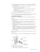
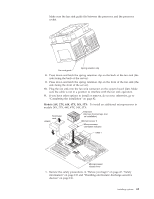
1. Review the information listed in "Before you begin" on page 47, "Safety information" on page 133 and "Handling electrostatic discharge-sensitive devices" on page 136. Also review the documentation that comes with the option. 2. Turn off the server and peripheral devices and disconnect all external cables and power cords; then, remove the cover. (See the "Removing the cover, door, and bezel" on page 48.) 3. Touch the static-protective package containing the DIMM to any unpainted metal surface on the server. Then, remove the DIMM from the package. You must install memory in matched pairs: the first pair must be in slots 1 and 4, and the second pair must be in slots 2 and 3. Attention: To avoid breaking the retaining clips or damaging the DIMM connectors, handle the clips gently. 4. Install the DIMM: a. Turn the DIMM so that the pins and keys align correctly with the connector. DIMM (second pair) b. Insert the DIMM into the connector by pressing on one edge of the DIMM and then on the other edge of the DIMM. Make sure to press the DIMM straight into the connector. Make sure that the retaining clips snap into the closed position. c. Make sure the retaining clips are in the closed position. If a gap exists between the DIMM and the retaining clips, the DIMM has not been properly installed. In this case, open the retaining clips and remove the DIMM; then, reinsert the DIMM. 5. Repeat steps 3 through 4 for the second DIMM; then, continue with step 6. 6. If you have other options to install or remove, do so now; otherwise, go to "Completing the installation" on page 82. 66 Hardware Maintenance Manual: xSeries 232, Type 8668
-
 1
1 -
2
-
3
-
4
-
5
-
6
-
7
-
8
-
9
-
10
-
11
-
12
-
13
-
14
-
15
-
16
-
17
-
18
-
19
-
20
-
21
-
22
-
23
-
24
-
25
-
26
-
27
-
28
-
29
-
30
-
31
-
32
-
33
-
34
-
35
-
36
-
37
-
38
-
39
-
40
-
41
-
42
-
43
-
44
-
45
-
46
-
47
-
48
-
49
-
50
-
51
-
52
-
53
-
54
-
55
-
56
-
57
-
58
-
59
-
60
-
61
-
62
-
63
-
64
-
65
-
66
-
67
-
68
-
 69
69 -
 70
70 -
 71
71 -
 72
72 -
 73
73 -
 74
74 -
 75
75 -
 76
76 -
 77
77 -
 78
78 -
 79
79 -
80
-
81
-
82
-
83
-
84
-
85
-
86
-
87
-
88
-
89
-
90
-
91
-
92
-
93
-
94
-
95
-
96
-
97
-
98
-
99
-
100
-
101
-
102
-
103
-
104
-
105
-
106
-
107
-
108
-
109
-
110
-
111
-
112
-
113
-
114
-
115
-
116
-
117
-
118
-
119
-
120
-
121
-
122
-
123
-
124
-
125
-
126
-
127
-
128
-
129
-
130
-
131
-
132
-
133
-
134
-
135
-
136
-
137
-
138
-
139
-
140
-
141
-
142
-
143
-
144
-
145
-
146
-
147
-
148
-
149
-
150
-
151
-
152
-
153
-
154
-
155
-
156
-
157
-
158
-
159
-
160
-
161
-
162
-
163
-
164
-
165
-
166
-
167
-
168
-
169
-
170
-
171
-
172
-
173
-
174
-
175
-
176
-
177
-
178
 |
 |
