IBM 8668 Hardware Maintenance Manual - Page 76
When installing or replacing a VRM, use only a VRM specified
 |
UPC - 087944723158
View all IBM 8668 manuals
Add to My Manuals
Save this manual to your list of manuals |
Page 76 highlights
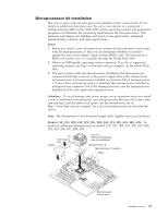
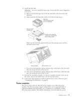
1. Review the safety precautions in "Before you begin" on page 47, "Safety information" on page 133 and "Handling electrostatic discharge-sensitive devices" on page 136. 2. Turn off the server and peripheral devices and disconnect all external cables and power cords; then remove the cover (see "Removing the cover, door, and bezel" on page 48 for details). 3. Remove the terminator card from the microprocessor connector. Store the terminator card in a safe place in the static-protective package that your new microprocessor comes in; you will need to install it again, if you ever remove the microprocessor and do not replace it. 4. Install the microprocessor: a. Touch the static-protective package containing the new microprocessor to any unpainted metal surface on the server; then, remove the microprocessor from the package. b. Line up the microprocessor pins over the microprocessor connector and carefully press the microprocessor into the connector. c. Press down and latch the release lever. Note: To remove a microprocessor, pull upward on the microprocessor release lever and then lift the microprocessor off of the connector. 5. Install the voltage regulator module (VRM) included in the microprocessor kit. Attention: When installing or replacing a VRM, use only a VRM specified for use with the xSeries 232 server. Use of other VRMs might cause the server to overheat. a. Center the VRM over the VRM connector. Make sure that the VRM is oriented and aligned correctly. Note: The VRM is keyed to be installed only one way. b. Press the VRM into the connector. Note: If you remove the microprocessor later, remember to install the terminator card in the appropriate microprocessor connector and to remove the VRM. 6. Remove the thermal tape liner from the underside of the fan sink and discard. 7. Set the fan sink into place. Fan sink (Remove thermal tape liner on installation) Microprocessor release lever Ensure correct alignment of fan sink, mounting clip, and mounting socket 68 Hardware Maintenance Manual: xSeries 232, Type 8668
-
 1
1 -
2
-
3
-
4
-
5
-
6
-
7
-
8
-
9
-
10
-
11
-
12
-
13
-
14
-
15
-
16
-
17
-
18
-
19
-
20
-
21
-
22
-
23
-
24
-
25
-
26
-
27
-
28
-
29
-
30
-
31
-
32
-
33
-
34
-
35
-
36
-
37
-
38
-
39
-
40
-
41
-
42
-
43
-
44
-
45
-
46
-
47
-
48
-
49
-
50
-
51
-
52
-
53
-
54
-
55
-
56
-
57
-
58
-
59
-
60
-
61
-
62
-
63
-
64
-
65
-
66
-
67
-
68
-
69
-
70
-
 71
71 -
 72
72 -
 73
73 -
 74
74 -
 75
75 -
 76
76 -
 77
77 -
 78
78 -
 79
79 -
 80
80 -
 81
81 -
82
-
83
-
84
-
85
-
86
-
87
-
88
-
89
-
90
-
91
-
92
-
93
-
94
-
95
-
96
-
97
-
98
-
99
-
100
-
101
-
102
-
103
-
104
-
105
-
106
-
107
-
108
-
109
-
110
-
111
-
112
-
113
-
114
-
115
-
116
-
117
-
118
-
119
-
120
-
121
-
122
-
123
-
124
-
125
-
126
-
127
-
128
-
129
-
130
-
131
-
132
-
133
-
134
-
135
-
136
-
137
-
138
-
139
-
140
-
141
-
142
-
143
-
144
-
145
-
146
-
147
-
148
-
149
-
150
-
151
-
152
-
153
-
154
-
155
-
156
-
157
-
158
-
159
-
160
-
161
-
162
-
163
-
164
-
165
-
166
-
167
-
168
-
169
-
170
-
171
-
172
-
173
-
174
-
175
-
176
-
177
-
178
 |
 |
