IBM 8668 Hardware Maintenance Manual - Page 77
models 24X, 2TX, 44X, 4TX, 54X, 5TX, To install an additional microprocessor
 |
UPC - 087944723158
View all IBM 8668 manuals
Add to My Manuals
Save this manual to your list of manuals |
Page 77 highlights
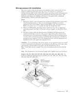
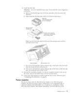
Make sure the fan sink guide fits between the processor and the processor socket. Fan sink guide Spring retention clip 8. Press down and latch the spring retention clip on the back of the fan sink (the side facing the back of the server). 9. Press down and latch the spring retention clip on the front of the fan sink (the side facing the front of the server). 10. Plug the fan sink into the fan sink connector on the system board (J46). Make sure the cable is not in a position to interfere with the fan sink operation. 11. If you have other options to install or remove, do so now; otherwise, go to "Completing the installation" on page 82. Models 24X, 2TX, 44X, 4TX, 54X, 5TX: To install an additional microprocessor in models 24X, 2TX, 44X, 4TX, 54X, 5TX: Terminator card VRM 2 Heat sink (Remove thermal tape liner on installation) Microprocessor 2 Microprocessor orientation indicator VRM 1 Microprocessor release lever 1. Review the safety precautions in "Before you begin" on page 47, "Safety information" on page 133 and "Handling electrostatic discharge-sensitive devices" on page 136. Installing options 69
-
 1
1 -
2
-
3
-
4
-
5
-
6
-
7
-
8
-
9
-
10
-
11
-
12
-
13
-
14
-
15
-
16
-
17
-
18
-
19
-
20
-
21
-
22
-
23
-
24
-
25
-
26
-
27
-
28
-
29
-
30
-
31
-
32
-
33
-
34
-
35
-
36
-
37
-
38
-
39
-
40
-
41
-
42
-
43
-
44
-
45
-
46
-
47
-
48
-
49
-
50
-
51
-
52
-
53
-
54
-
55
-
56
-
57
-
58
-
59
-
60
-
61
-
62
-
63
-
64
-
65
-
66
-
67
-
68
-
69
-
70
-
71
-
 72
72 -
 73
73 -
 74
74 -
 75
75 -
 76
76 -
 77
77 -
 78
78 -
 79
79 -
 80
80 -
 81
81 -
 82
82 -
83
-
84
-
85
-
86
-
87
-
88
-
89
-
90
-
91
-
92
-
93
-
94
-
95
-
96
-
97
-
98
-
99
-
100
-
101
-
102
-
103
-
104
-
105
-
106
-
107
-
108
-
109
-
110
-
111
-
112
-
113
-
114
-
115
-
116
-
117
-
118
-
119
-
120
-
121
-
122
-
123
-
124
-
125
-
126
-
127
-
128
-
129
-
130
-
131
-
132
-
133
-
134
-
135
-
136
-
137
-
138
-
139
-
140
-
141
-
142
-
143
-
144
-
145
-
146
-
147
-
148
-
149
-
150
-
151
-
152
-
153
-
154
-
155
-
156
-
157
-
158
-
159
-
160
-
161
-
162
-
163
-
164
-
165
-
166
-
167
-
168
-
169
-
170
-
171
-
172
-
173
-
174
-
175
-
176
-
177
-
178
 |
 |
