IBM 8668 Hardware Maintenance Manual - Page 71
parts inside the device., result in exposure to hazardous laser radiation. There are no serviceable
 |
UPC - 087944723158
View all IBM 8668 manuals
Add to My Manuals
Save this manual to your list of manuals |
Page 71 highlights
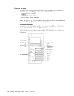
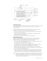
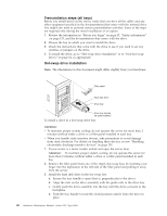
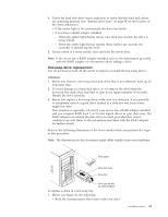
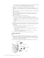
To install a non-hot-swap drive (5.25-inch, removable media) in one of the non-hot-swap bays: 1. Read the information in "Preinstallation steps (all bays)" on page 60. 2. Turn off the server and peripheral devices and then remove the cover and the bezel (see "Removing the cover, door, and bezel" on page 48 for details). 3. Remove the filler panel from the bay opening by pulling the filler panel away from the server. You do not need the filler panel when you have a drive installed in the bay. 4. If the drive that you are installing is a laser product, observe the following safety precaution. Statement 3: CAUTION: When laser products (such as CD-ROMs, DVD drives, fiber optic devices, or transmitters) are installed, note the following: v Do not remove the covers. Removing the covers of the laser product could result in exposure to hazardous laser radiation. There are no serviceable parts inside the device. v Use of controls or adjustments or performance of procedures other than those specified herein might result in hazardous radiation exposure. DANGER: Some laser products contain an embedded Class 3A or Class 3B laser diode. Note the following: Laser radiation when open. Do not stare into the beam, do not view directly with optical instruments, and avoid direct exposure to the beam. 5. Touch the static-protective package containing the drive to any unpainted metal surface on the server; then, remove the drive from the package and place it on a static-protective surface. 6. Set any jumpers or switches on the drive according to the documentation that comes with the drive. 7. Install rails on the drive. v If you are installing a standard-size drive: a. Pull the blue slide rails off the back of the filler panel. b. Clip the rails onto the sides of the drive. v If you are installing a digital linear tape (DLT) backup drive, use the metal slide rails and screws that come in the box that contains the server documentation. 8. Align the rails on the drive with the guide rails in the drive bay. 9. Push the drive into the bay until it clicks into place. 10. If the drive is an IDE device: a. Make sure the drive is not a hard disk drive. b. Plug a connector on the IDE cable into the back of the drive. Installing options 63
-
 1
1 -
2
-
3
-
4
-
5
-
6
-
7
-
8
-
9
-
10
-
11
-
12
-
13
-
14
-
15
-
16
-
17
-
18
-
19
-
20
-
21
-
22
-
23
-
24
-
25
-
26
-
27
-
28
-
29
-
30
-
31
-
32
-
33
-
34
-
35
-
36
-
37
-
38
-
39
-
40
-
41
-
42
-
43
-
44
-
45
-
46
-
47
-
48
-
49
-
50
-
51
-
52
-
53
-
54
-
55
-
56
-
57
-
58
-
59
-
60
-
61
-
62
-
63
-
64
-
65
-
 66
66 -
 67
67 -
 68
68 -
 69
69 -
 70
70 -
 71
71 -
 72
72 -
 73
73 -
 74
74 -
 75
75 -
 76
76 -
77
-
78
-
79
-
80
-
81
-
82
-
83
-
84
-
85
-
86
-
87
-
88
-
89
-
90
-
91
-
92
-
93
-
94
-
95
-
96
-
97
-
98
-
99
-
100
-
101
-
102
-
103
-
104
-
105
-
106
-
107
-
108
-
109
-
110
-
111
-
112
-
113
-
114
-
115
-
116
-
117
-
118
-
119
-
120
-
121
-
122
-
123
-
124
-
125
-
126
-
127
-
128
-
129
-
130
-
131
-
132
-
133
-
134
-
135
-
136
-
137
-
138
-
139
-
140
-
141
-
142
-
143
-
144
-
145
-
146
-
147
-
148
-
149
-
150
-
151
-
152
-
153
-
154
-
155
-
156
-
157
-
158
-
159
-
160
-
161
-
162
-
163
-
164
-
165
-
166
-
167
-
168
-
169
-
170
-
171
-
172
-
173
-
174
-
175
-
176
-
177
-
178
 |
 |
