IBM 8668 Hardware Maintenance Manual - Page 72
Installing an xSeries 3-Pack Ultra160 Hot-Swap Expansion Kit
 |
UPC - 087944723158
View all IBM 8668 manuals
Add to My Manuals
Save this manual to your list of manuals |
Page 72 highlights
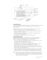
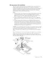
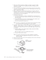
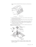
c. Make sure the other end of the IDE cable is plugged into the IDE connector on the system board. d. Go to step 12 11. If the drive is a SCSI device: a. Make sure the drive is not a hard disk drive. b. Connect one of the connectors on the SCSI cable to the back of the drive. c. Connect the other end of the SCSI cable to the SCSI channel B connector on the system board, or to an optional SCSI adapter, as appropriate. See "System board internal cable connectors" on page 41 for the location of the SCSI connectors. See also "Ultra160 SCSI ports" on page 93 for information about SCSI connections and devices. 12. Connect a power cable to the back of the device. Power cables for non-hot-swap drives come installed in your server. The connectors are keyed and can be inserted only one way. 13. If you are installing another non-hot-swap drive, do so at this time. Otherwise, continue with the next step. 14. If you have other options to install or remove, do so now; otherwise, replace the cover (see "Completing the installation" on page 82 for details). Installing an xSeries 3-Pack Ultra160 Hot-Swap Expansion Kit You can install an xSeries 3-Pack Ultra160 Hot-Swap Expansion Kit in your server to support three additional hot-swap hard disk drives. Note: The illustrations in this document might differ slightly from your hardware. Filler panels Hot-swap expansion option To install an xSeries 3-Pack Ultra160 Hot-Swap Expansion Kit: 1. Review the information in "Before you begin" on page 47, "Safety information" on page 133, and "Handling electrostatic discharge-sensitive devices" on page 136. 2. Turn off the server and peripheral devices and disconnect all external cables and power cords; then, remove the cover and bezel. (See "Removing the cover, door, and bezel" on page 48.) 3. Release the side rails to remove the filler panels from the bays below the CD-ROM drive. 4. Refer to the documentation provided with the option to assemble the hot-swap expansion option. 64 Hardware Maintenance Manual: xSeries 232, Type 8668
-
 1
1 -
2
-
3
-
4
-
5
-
6
-
7
-
8
-
9
-
10
-
11
-
12
-
13
-
14
-
15
-
16
-
17
-
18
-
19
-
20
-
21
-
22
-
23
-
24
-
25
-
26
-
27
-
28
-
29
-
30
-
31
-
32
-
33
-
34
-
35
-
36
-
37
-
38
-
39
-
40
-
41
-
42
-
43
-
44
-
45
-
46
-
47
-
48
-
49
-
50
-
51
-
52
-
53
-
54
-
55
-
56
-
57
-
58
-
59
-
60
-
61
-
62
-
63
-
64
-
65
-
66
-
 67
67 -
 68
68 -
 69
69 -
 70
70 -
 71
71 -
 72
72 -
 73
73 -
 74
74 -
 75
75 -
 76
76 -
 77
77 -
78
-
79
-
80
-
81
-
82
-
83
-
84
-
85
-
86
-
87
-
88
-
89
-
90
-
91
-
92
-
93
-
94
-
95
-
96
-
97
-
98
-
99
-
100
-
101
-
102
-
103
-
104
-
105
-
106
-
107
-
108
-
109
-
110
-
111
-
112
-
113
-
114
-
115
-
116
-
117
-
118
-
119
-
120
-
121
-
122
-
123
-
124
-
125
-
126
-
127
-
128
-
129
-
130
-
131
-
132
-
133
-
134
-
135
-
136
-
137
-
138
-
139
-
140
-
141
-
142
-
143
-
144
-
145
-
146
-
147
-
148
-
149
-
150
-
151
-
152
-
153
-
154
-
155
-
156
-
157
-
158
-
159
-
160
-
161
-
162
-
163
-
164
-
165
-
166
-
167
-
168
-
169
-
170
-
171
-
172
-
173
-
174
-
175
-
176
-
177
-
178
 |
 |
