IBM 867431X Hardware Maintenance Manual - Page 103
Console ports, Device breakout cable, Keyboard connector, Auxiliary-device (pointing device) connector
 |
View all IBM 867431X manuals
Add to My Manuals
Save this manual to your list of manuals |
Page 103 highlights
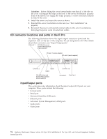
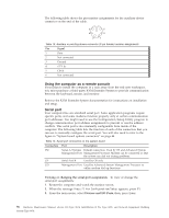
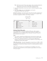
Console ports There are two console ports on the rear of your computer labeled IN and OUT. Use only the OUT port to connect the computer to the console (mouse and keyboard). Device breakout cable A keyboard and mouse or pointing device are connected to your computer through the device breakout cable. The keyboard and mouse cables have icons of a keyboard and a mouse on their respective cable connectors for easy identification. Note: Do not use the monitor connector on this device breakout cable. Instead, use the monitor connector cables that comes with the video adapter. The part numbers for these cables are P/N 15912-01 and P/N 15941-00. Keyboard connector: There is one keyboard connector on the end of the device breakout cable. This connector is identified by the keyboard icon. Note: If you attach a standard (non-USB) keyboard to the keyboard connector, the USB ports and devices will be disabled during the power-on self-test (POST). The following table shows the pin-number assignments for the keyboard connector on the end of the cable. 6 4 2 5 3 1 Table 12. Keyboard-connector (6-pin female) number assignments Pin I/O Signal 1 I/O Data 2 N/A Reserved 3 N/A Ground 4 N/A +5 V dc 5 I/O Keyboard clock 6 N/A Reserved Auxiliary-device (pointing device) connector: On the end of the device breakout cable, there is one auxiliary-device connector that supports a mouse or other pointing device. This connector is identified by the mouse icon. Installing options 95
-
 1
1 -
2
-
3
-
4
-
5
-
6
-
7
-
8
-
9
-
10
-
11
-
12
-
13
-
14
-
15
-
16
-
17
-
18
-
19
-
20
-
21
-
22
-
23
-
24
-
25
-
26
-
27
-
28
-
29
-
30
-
31
-
32
-
33
-
34
-
35
-
36
-
37
-
38
-
39
-
40
-
41
-
42
-
43
-
44
-
45
-
46
-
47
-
48
-
49
-
50
-
51
-
52
-
53
-
54
-
55
-
56
-
57
-
58
-
59
-
60
-
61
-
62
-
63
-
64
-
65
-
66
-
67
-
68
-
69
-
70
-
71
-
72
-
73
-
74
-
75
-
76
-
77
-
78
-
79
-
80
-
81
-
82
-
83
-
84
-
85
-
86
-
87
-
88
-
89
-
90
-
91
-
92
-
93
-
94
-
95
-
96
-
97
-
 98
98 -
 99
99 -
 100
100 -
 101
101 -
 102
102 -
 103
103 -
 104
104 -
 105
105 -
 106
106 -
 107
107 -
 108
108 -
109
-
110
-
111
-
112
-
113
-
114
-
115
-
116
-
117
-
118
-
119
-
120
-
121
-
122
-
123
-
124
-
125
-
126
-
127
-
128
-
129
-
130
-
131
-
132
-
133
-
134
-
135
-
136
-
137
-
138
-
139
-
140
-
141
-
142
-
143
-
144
-
145
-
146
-
147
-
148
-
149
-
150
-
151
-
152
-
153
-
154
-
155
-
156
-
157
-
158
-
159
-
160
-
161
-
162
-
163
-
164
-
165
-
166
-
167
-
168
-
169
-
170
-
171
-
172
-
173
-
174
-
175
-
176
-
177
-
178
-
179
-
180
-
181
-
182
-
183
-
184
-
185
-
186
-
187
-
188
-
189
-
190
-
191
-
192
 |
 |
