IBM 867431X Hardware Maintenance Manual - Page 109
Ethernet port connector, Advanced System Management ports, Network icon, Control Panel, Adapters
 |
View all IBM 867431X manuals
Add to My Manuals
Save this manual to your list of manuals |
Page 109 highlights
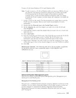
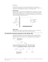
To join a VLAN from Windows NT 4.0 and Windows 2000: Note: To add or remove a VLAN in Windows 2000, you must use PROSet. Do not use Network and Dial-up Connections dialog boxes to enable and disable VLANs because the VLAN driver might not be enabled or disabled correctly. Once a VLAN has been disabled in Windows 2000, you cannot re-enable the VLAN. Instead, you must restart the computer to re-enable the connection. 1. Create a VLAN on the switch. Use the parameters you assign there to join the VLAN from the computer. Refer to your switch documentation for more information. 2. Double-click the Network icon in the Control Panel window. 3. On the Adapters tab, select the adapter you want to be on the VLAN and select Properties. 4. In the PROSet window, select the adapter that you want to be on a VLAN and right-click on it. 5. Select Add VLAN. 6. Enter the VLAN ID and VLAN name. The VLAN ID must match the VLAN ID of the switch. The ID range is from 1 to 4094. The VLAN name is for information only and does not need to match the name on the switch. 7. Repeat steps 3 through 5 for each VLAN you want the computer to join. Click on the plus sign (+) next to the selected adapter to view the VLANs you added. 8. Click OK. Ethernet port connector: The following table shows the pin-number assignments for the RJ-45 connector. These assignments apply to both 10BASE-T and 100BASE-TX devices. Table 17. Ethernet RJ-45 connector pin-number assignments. Pin Signal Pin 1 Transmit data+ 5 2 Transmit data- 6 3 Receive data+ 7 4 Not connected 8 Signal Not connected Receive data Not connected Not connected Advanced System Management ports There are two kinds of Advanced System Management ports: Management port (Serial port A) and RS-485 ports. Management Port (Serial port A) This port uses a standard D-shell serial-port connector, labeled A on the rear of the computer. You can attach a dedicated modem to the D-shell connector on the rear of your computer to communicate with the integrated Advanced System Management Processor. For more information about the serial port, see "Serial port" on page 96. Installing options 101
-
 1
1 -
2
-
3
-
4
-
5
-
6
-
7
-
8
-
9
-
10
-
11
-
12
-
13
-
14
-
15
-
16
-
17
-
18
-
19
-
20
-
21
-
22
-
23
-
24
-
25
-
26
-
27
-
28
-
29
-
30
-
31
-
32
-
33
-
34
-
35
-
36
-
37
-
38
-
39
-
40
-
41
-
42
-
43
-
44
-
45
-
46
-
47
-
48
-
49
-
50
-
51
-
52
-
53
-
54
-
55
-
56
-
57
-
58
-
59
-
60
-
61
-
62
-
63
-
64
-
65
-
66
-
67
-
68
-
69
-
70
-
71
-
72
-
73
-
74
-
75
-
76
-
77
-
78
-
79
-
80
-
81
-
82
-
83
-
84
-
85
-
86
-
87
-
88
-
89
-
90
-
91
-
92
-
93
-
94
-
95
-
96
-
97
-
98
-
99
-
100
-
101
-
102
-
103
-
 104
104 -
 105
105 -
 106
106 -
 107
107 -
 108
108 -
 109
109 -
 110
110 -
 111
111 -
 112
112 -
 113
113 -
 114
114 -
115
-
116
-
117
-
118
-
119
-
120
-
121
-
122
-
123
-
124
-
125
-
126
-
127
-
128
-
129
-
130
-
131
-
132
-
133
-
134
-
135
-
136
-
137
-
138
-
139
-
140
-
141
-
142
-
143
-
144
-
145
-
146
-
147
-
148
-
149
-
150
-
151
-
152
-
153
-
154
-
155
-
156
-
157
-
158
-
159
-
160
-
161
-
162
-
163
-
164
-
165
-
166
-
167
-
168
-
169
-
170
-
171
-
172
-
173
-
174
-
175
-
176
-
177
-
178
-
179
-
180
-
181
-
182
-
183
-
184
-
185
-
186
-
187
-
188
-
189
-
190
-
191
-
192
 |
 |
