IBM 867431X Hardware Maintenance Manual - Page 94
The DIMM has two index slots, one in the center and the other
 |
View all IBM 867431X manuals
Add to My Manuals
Save this manual to your list of manuals |
Page 94 highlights
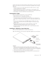
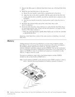
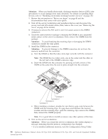
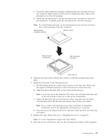
Attention: When you handle electrostatic discharge-sensitive devices (ESD), take precautions to avoid damage from static electricity. For details on handling these devices, refer to "Handling electrostatic discharge-sensitive devices" on page 150. 1. Review the information in "Before you begin" on page 45 and the documentation that comes with your option. 2. Turn off the server/workstation and peripheral devices and disconnect the power cord and all external cables; then, remove the cover (see "Removing the cover" on page 48 for details). 3. If necessary, remove the PCI card in slot 2 for easier access to the DIMM connectors. 4. Touch the static-protective package containing the DIMM to any unpainted metal surface on the server/workstation. Then, remove the DIMM from the package. Attention: To avoid breaking the retaining clips or damaging the DIMM connectors, handle the clips gently. 5. Install the DIMM in the connector. Attention: To prevent damage to the DIMM connectors do not force the memory module into the connector. a. Turn the DIMM so that the index slots align correctly with the connector. Note: The DIMM has two index slots, one in the center and the other on the left half of the DIMMS connector edge. b. Insert the DIMM into the connector by pressing on both corners of the DIMM at the same time. Be sure to press straight into the connector. Connector 1 Connector 2 Connector 3 Connector 4 c. When installing a memory module be sure that no gap exists between the DIMM and the retaining clips. If a gap does exist between the memory module and the retaining clips: open the retaining clips, remove the DIMM; then, reinsert the DIMM properly. Note: It is a good idea to install or remove any other options at this time. 6. Turn on the server/workstation. Attention: When you restart the server/workstation, the system displays a message indicating that the memory configuration has changed. v If you installed additional memory, start the Configuration/Setup Utility 86 Hardware Maintenance Manual: xSeries 330 Type 8674, IntelliStation R Pro Type 6851, and Network Equipment Building System Type 8674
-
 1
1 -
2
-
3
-
4
-
5
-
6
-
7
-
8
-
9
-
10
-
11
-
12
-
13
-
14
-
15
-
16
-
17
-
18
-
19
-
20
-
21
-
22
-
23
-
24
-
25
-
26
-
27
-
28
-
29
-
30
-
31
-
32
-
33
-
34
-
35
-
36
-
37
-
38
-
39
-
40
-
41
-
42
-
43
-
44
-
45
-
46
-
47
-
48
-
49
-
50
-
51
-
52
-
53
-
54
-
55
-
56
-
57
-
58
-
59
-
60
-
61
-
62
-
63
-
64
-
65
-
66
-
67
-
68
-
69
-
70
-
71
-
72
-
73
-
74
-
75
-
76
-
77
-
78
-
79
-
80
-
81
-
82
-
83
-
84
-
85
-
86
-
87
-
88
-
 89
89 -
 90
90 -
 91
91 -
 92
92 -
 93
93 -
 94
94 -
 95
95 -
 96
96 -
 97
97 -
 98
98 -
 99
99 -
100
-
101
-
102
-
103
-
104
-
105
-
106
-
107
-
108
-
109
-
110
-
111
-
112
-
113
-
114
-
115
-
116
-
117
-
118
-
119
-
120
-
121
-
122
-
123
-
124
-
125
-
126
-
127
-
128
-
129
-
130
-
131
-
132
-
133
-
134
-
135
-
136
-
137
-
138
-
139
-
140
-
141
-
142
-
143
-
144
-
145
-
146
-
147
-
148
-
149
-
150
-
151
-
152
-
153
-
154
-
155
-
156
-
157
-
158
-
159
-
160
-
161
-
162
-
163
-
164
-
165
-
166
-
167
-
168
-
169
-
170
-
171
-
172
-
173
-
174
-
175
-
176
-
177
-
178
-
179
-
180
-
181
-
182
-
183
-
184
-
185
-
186
-
187
-
188
-
189
-
190
-
191
-
192
 |
 |
