IBM 867431X Hardware Maintenance Manual - Page 97
over the heat sink with the heat sink release lever in the up position.
 |
View all IBM 867431X manuals
Add to My Manuals
Save this manual to your list of manuals |
Page 97 highlights
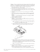
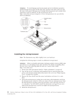
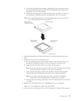
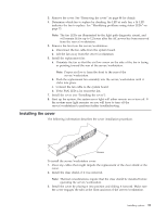
a. Touch the static-protective package containing the new microprocessor to any unpainted metal surface on the server/workstation; then, remove the microprocessor from the package. b. Orient the microprocessor over the microprocessor connector as shown in the illustration. Carefully press the microprocessor into the connector. Note: To avoid bending the pins on the microprocessor, do not use excessive force when pressing it into the connector. Microprocessor orientation indicator Microprocessor Microprocessorrelease lever Microprocessor connector Rear of server 6. Push the microprocessor release lever down to lock the microprocessor into place. 7. Install the heat sink on the microprocessor: a. Peel the plastic protective strip off the bottom of the heat sink. Make sure the square of thermal material is still on the bottom of the heat sink. b. Align and place the heat sink on top of the microprocessor. Note: Locate the slot in the channel of the heat sink. Orientate the heat sink so the slot will be at the rear of the server/workstation. c. Align and place the clip over the heat sin; then, snap the clip into place over the heat sink with the heat sink release lever in the up position. Note: If you remove the microprocessor later, remember to install the terminator card in the appropriate microprocessor connector. d. Press the heat sink release lever down into the locked position once the clip is in place. 8. Replace the clear shield, then go to "Installing the cover" on page 93. Note: It is very important to replace the clear shield. 9. Start the server/workstation and run the Configuration/Setup Utility program. Installing options 89
-
 1
1 -
2
-
3
-
4
-
5
-
6
-
7
-
8
-
9
-
10
-
11
-
12
-
13
-
14
-
15
-
16
-
17
-
18
-
19
-
20
-
21
-
22
-
23
-
24
-
25
-
26
-
27
-
28
-
29
-
30
-
31
-
32
-
33
-
34
-
35
-
36
-
37
-
38
-
39
-
40
-
41
-
42
-
43
-
44
-
45
-
46
-
47
-
48
-
49
-
50
-
51
-
52
-
53
-
54
-
55
-
56
-
57
-
58
-
59
-
60
-
61
-
62
-
63
-
64
-
65
-
66
-
67
-
68
-
69
-
70
-
71
-
72
-
73
-
74
-
75
-
76
-
77
-
78
-
79
-
80
-
81
-
82
-
83
-
84
-
85
-
86
-
87
-
88
-
89
-
90
-
91
-
 92
92 -
 93
93 -
 94
94 -
 95
95 -
 96
96 -
 97
97 -
 98
98 -
 99
99 -
 100
100 -
 101
101 -
 102
102 -
103
-
104
-
105
-
106
-
107
-
108
-
109
-
110
-
111
-
112
-
113
-
114
-
115
-
116
-
117
-
118
-
119
-
120
-
121
-
122
-
123
-
124
-
125
-
126
-
127
-
128
-
129
-
130
-
131
-
132
-
133
-
134
-
135
-
136
-
137
-
138
-
139
-
140
-
141
-
142
-
143
-
144
-
145
-
146
-
147
-
148
-
149
-
150
-
151
-
152
-
153
-
154
-
155
-
156
-
157
-
158
-
159
-
160
-
161
-
162
-
163
-
164
-
165
-
166
-
167
-
168
-
169
-
170
-
171
-
172
-
173
-
174
-
175
-
176
-
177
-
178
-
179
-
180
-
181
-
182
-
183
-
184
-
185
-
186
-
187
-
188
-
189
-
190
-
191
-
192
 |
 |
