Ricoh 5510L Operating Instructions - Page 27
Rear View - changing the toner
 |
View all Ricoh 5510L manuals
Add to My Manuals
Save this manual to your list of manuals |
Page 27 highlights
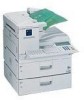
Rear View The following illustration is for Type1. Guide to Components 1 1. Handset / External Telephone Connector 2. G3 Line Connector 3. Manual Pocket 4. Original Bypass Tray Set non-standard size originals here. 5. Main Side Cover Open this cover when changing the toner cartridge or installing the fusing maintenance unit. 6. Bypass Tray Cover Open when the optional bypass tray unit is installed. 7. Paper Tray Side Cover Open to clear paper jams. 19
-
 1
1 -
2
-
3
-
4
-
5
-
6
-
7
-
8
-
9
-
10
-
11
-
12
-
13
-
14
-
15
-
16
-
17
-
18
-
19
-
20
-
21
-
 22
22 -
 23
23 -
 24
24 -
 25
25 -
 26
26 -
 27
27 -
 28
28 -
 29
29 -
 30
30 -
 31
31 -
 32
32 -
33
-
34
-
35
-
36
-
37
-
38
-
39
-
40
-
41
-
42
-
43
-
44
-
45
-
46
-
47
-
48
-
49
-
50
-
51
-
52
-
53
-
54
-
55
-
56
-
57
-
58
-
59
-
60
-
61
-
62
-
63
-
64
-
65
-
66
-
67
-
68
-
69
-
70
-
71
-
72
-
73
-
74
-
75
-
76
-
77
-
78
-
79
-
80
-
81
-
82
-
83
-
84
-
85
-
86
-
87
-
88
-
89
-
90
-
91
-
92
-
93
-
94
-
95
-
96
-
97
-
98
-
99
-
100
-
101
-
102
-
103
-
104
-
105
-
106
-
107
-
108
-
109
-
110
-
111
-
112
-
113
-
114
-
115
-
116
-
117
-
118
-
119
-
120
-
121
-
122
-
123
-
124
-
125
-
126
-
127
-
128
 |
 |

Guide to Components
19
1
Rear View
The following illustration is for Type1.
1.
Handset / External Telephone
Connector
2.
G3 Line Connector
3.
Manual Pocket
4.
Original Bypass Tray
Set non-standard size originals here.
5.
Main Side Cover
Open this cover when changing the toner
cartridge or installing the fusing mainte-
nance unit.
6.
Bypass Tray Cover
Open when the optional bypass tray unit
is installed.
7.
Paper Tray Side Cover
Open to clear paper jams.