3Com 3C13886 Installation Guide - Page 101
Interface Cable, Connection of the Interface Cable, Table 3-35, Meaning
 |
UPC - 662705478456
View all 3Com 3C13886 manuals
Add to My Manuals
Save this manual to your list of manuals |
Page 101 highlights
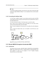
3Com Router Module Guide Chapter 3 Multifunctional Interface Modules The LEDs on the front panel of the ROUTER 4-PORT E1 IMA MIM interface card, as described in the following table: Table 3-35 Meaning of the LEDs LED Meaning OFF: the link is disconnected. LINK ON: the link is connected. Blink: data is being transmitted/received. ACT Off: no data is being transmitted/received. 3.14.5 Interface Cable The RT-ROUTER 4-PORT E1 IMA MIM provides four E1 ports and adopts a 120-ohm or a 75-ohm ROUTER 4-PORT E1 IMA MIM conversion cable. The two types of cables have similar appearance. Both of them have a DB68 connector at one end used to connect a router. While at the other end, the 75-ohm ROUTER 4-PORT E1 IMA MIM conversion cable can be connected with eight coaxial cables; and the 120-ohm ROUTER 4-PORT E1 IMA MIM conversion cable can be connected with four twisted pairs. 3.14.6 Connection of the Interface Cable Perform the following procedure to connect the RT-ROUTER 4-PORT E1 IMA MIM interface cable: 1) Choose an appropriate type of IMA-8E1/ROUTER 4-PORT E1 IMA MIM cable depending on the interface type of the peer device. z If the interface impedance of the peer device is 75 ohm, use a 75-ohm ROUTER 4-PORT E1 IMA MIM conversion cable. z If the interface impedance of the peer device is 120 ohm, use a 120-ohm ROUTER 4-PORT E1 IMA MIM conversion cable. 2) Insert the ROUTER 4-PORT E1 IMA MIM conversion cable at the DB68 end to the DB68 port of the ROUTER 4-PORT E1 IMA MIM interface card, and fasten the fixed screws of the cable. 3) Check the serial number of the other end of the IMA-4E1 conversion cable and connect it with an E1 cable. 4) Connect the E1 cable with a peer device. 5) Check the slot-corresponding LED on the front panel of the router after power-on. If the LED lights, it indicates the interface card passed the self test and operates 3-57
-
 1
1 -
2
-
3
-
4
-
5
-
6
-
7
-
8
-
9
-
10
-
11
-
12
-
13
-
14
-
15
-
16
-
17
-
18
-
19
-
20
-
21
-
22
-
23
-
24
-
25
-
26
-
27
-
28
-
29
-
30
-
31
-
32
-
33
-
34
-
35
-
36
-
37
-
38
-
39
-
40
-
41
-
42
-
43
-
44
-
45
-
46
-
47
-
48
-
49
-
50
-
51
-
52
-
53
-
54
-
55
-
56
-
57
-
58
-
59
-
60
-
61
-
62
-
63
-
64
-
65
-
66
-
67
-
68
-
69
-
70
-
71
-
72
-
73
-
74
-
75
-
76
-
77
-
78
-
79
-
80
-
81
-
82
-
83
-
84
-
85
-
86
-
87
-
88
-
89
-
90
-
91
-
92
-
93
-
94
-
95
-
 96
96 -
 97
97 -
 98
98 -
 99
99 -
 100
100 -
 101
101 -
 102
102 -
 103
103 -
 104
104 -
 105
105 -
 106
106 -
107
-
108
-
109
-
110
-
111
-
112
-
113
-
114
-
115
-
116
-
117
-
118
-
119
-
120
-
121
-
122
-
123
-
124
-
125
-
126
-
127
-
128
-
129
-
130
-
131
-
132
-
133
-
134
-
135
-
136
-
137
-
138
-
139
-
140
-
141
-
142
-
143
-
144
-
145
-
146
-
147
-
148
-
149
-
150
-
151
-
152
-
153
-
154
-
155
-
156
-
157
-
158
-
159
-
160
-
161
-
162
-
163
-
164
-
165
-
166
-
167
-
168
-
169
-
170
-
171
 |
 |
