3Com 3C13886 Installation Guide - Page 159
Panel and Interface LEDs, Interface Optical Fiber, Connecting the Interface Optical Fiber,
 |
UPC - 662705478456
View all 3Com 3C13886 manuals
Add to My Manuals
Save this manual to your list of manuals |
Page 159 highlights
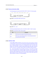
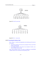
3Com Router Module Guide 4.14.3 Panel and Interface LEDs Chapter 4 The following figure illustrates the ROUTER 1-PORT OC3 POS FIC panel: Figure 4-47 ROUTER 1-PORT OC3 POS FIC panel The following table describes the LEDs on the ROUTER 1-PORT OC3 POS FIC panel. Table 4-32 LEDs on the ROUTER 1-PORT OC3 POS FIC panel LED Description LINK OFF means no link is present; ON means a link is present. OFF means no data is being transmitted or received; blinking means data is being ACT received or/and transmitted. 4.14.4 Interface Optical Fiber Like the FICCPOS, the ROUTER 1-PORT OC3 POS FIC uses optical fibers with LC-type connectors (see Error! Reference source not found.). 4.14.5 Connecting the Interface Optical Fiber Step 1: Insert the SFP card into its corresponding slot. Step 2: Locate the Rx and Tx fiber-optic interfaces on the interface card. Use two fibers to connect the ROUTER 1-PORT OC3 POS FIC to another device: Rx to Tx and Tx to Rx. Step 3: Power on the device and check the LINK LED on the ROUTER 1-PORT OC3 POS FIC panel: ON means the Rx link is present and OFF means the opposite. In the latter case, check the line status. Warning: Because invisible laser radiation may be emitted from the aperture of an optical port when no fiber is connected or the dust cap is removed, do not stare into the open aperture. Replace the dust cap when no fiber is connected to the optical port. 4-50
-
 1
1 -
2
-
3
-
4
-
5
-
6
-
7
-
8
-
9
-
10
-
11
-
12
-
13
-
14
-
15
-
16
-
17
-
18
-
19
-
20
-
21
-
22
-
23
-
24
-
25
-
26
-
27
-
28
-
29
-
30
-
31
-
32
-
33
-
34
-
35
-
36
-
37
-
38
-
39
-
40
-
41
-
42
-
43
-
44
-
45
-
46
-
47
-
48
-
49
-
50
-
51
-
52
-
53
-
54
-
55
-
56
-
57
-
58
-
59
-
60
-
61
-
62
-
63
-
64
-
65
-
66
-
67
-
68
-
69
-
70
-
71
-
72
-
73
-
74
-
75
-
76
-
77
-
78
-
79
-
80
-
81
-
82
-
83
-
84
-
85
-
86
-
87
-
88
-
89
-
90
-
91
-
92
-
93
-
94
-
95
-
96
-
97
-
98
-
99
-
100
-
101
-
102
-
103
-
104
-
105
-
106
-
107
-
108
-
109
-
110
-
111
-
112
-
113
-
114
-
115
-
116
-
117
-
118
-
119
-
120
-
121
-
122
-
123
-
124
-
125
-
126
-
127
-
128
-
129
-
130
-
131
-
132
-
133
-
134
-
135
-
136
-
137
-
138
-
139
-
140
-
141
-
142
-
143
-
144
-
145
-
146
-
147
-
148
-
149
-
150
-
151
-
152
-
153
-
 154
154 -
 155
155 -
 156
156 -
 157
157 -
 158
158 -
 159
159 -
 160
160 -
 161
161 -
 162
162 -
 163
163 -
 164
164 -
165
-
166
-
167
-
168
-
169
-
170
-
171
 |
 |
