3Com 3C13886 Installation Guide - Page 19
Appearance, II. DTE and DCE
 |
UPC - 662705478456
View all 3Com 3C13886 manuals
Add to My Manuals
Save this manual to your list of manuals |
Page 19 highlights
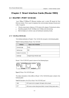
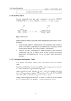
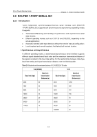
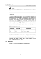
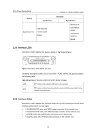
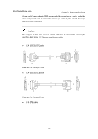
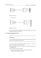
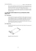
3Com Router Module Guide Chapter 2 Smart Interface Cards Caution: The baud rate cannot exceed 64 kbps if V.24 cable is used and the interface operates in synchronous mode. II. DTE and DCE The synchronous serial interface supports both DTE (Data Terminal Equipment) and DCE (Data Circuit-terminating Equipment) operating modes. Given that two devices are directly connected, if one operates in the DTE mode, the other will operate in the DCE mode. The DCE device provides the synchronous clock and specifies the communicating rate. The DTE device receives the synchronous clock and communicates at the specified rate. Generally, the Router is used as a DTE device. To make sure that the device is a DTE or DCE, refer to the manual shipped with this device. In addition, the following table may also help you to identify the type of the device. Table 2-4 Typical DTE and DCE equipment Equipment type Interface type Typical equipment DTE Male PC, Router DCE Female Modem, Multiplexer, CSU/DSU Asynchronous serial interface is generally used as dialing port and connected to a modem or a Terminal Adapter (TA). In this case, regardless of the operating mode of the device, only an appropriate baud rate for the interface needs to be selected. Synchronous serial interface is generally used for the direct connection to such a device as DDN, frame relay, or X.25 switch. 2.2.2 Appearance ROUTER 1-PORT SERIAL SIC is illustrated in the following figure: 2-4
-
 1
1 -
2
-
3
-
4
-
5
-
6
-
7
-
8
-
9
-
10
-
11
-
12
-
13
-
 14
14 -
 15
15 -
 16
16 -
 17
17 -
 18
18 -
 19
19 -
 20
20 -
 21
21 -
 22
22 -
 23
23 -
 24
24 -
25
-
26
-
27
-
28
-
29
-
30
-
31
-
32
-
33
-
34
-
35
-
36
-
37
-
38
-
39
-
40
-
41
-
42
-
43
-
44
-
45
-
46
-
47
-
48
-
49
-
50
-
51
-
52
-
53
-
54
-
55
-
56
-
57
-
58
-
59
-
60
-
61
-
62
-
63
-
64
-
65
-
66
-
67
-
68
-
69
-
70
-
71
-
72
-
73
-
74
-
75
-
76
-
77
-
78
-
79
-
80
-
81
-
82
-
83
-
84
-
85
-
86
-
87
-
88
-
89
-
90
-
91
-
92
-
93
-
94
-
95
-
96
-
97
-
98
-
99
-
100
-
101
-
102
-
103
-
104
-
105
-
106
-
107
-
108
-
109
-
110
-
111
-
112
-
113
-
114
-
115
-
116
-
117
-
118
-
119
-
120
-
121
-
122
-
123
-
124
-
125
-
126
-
127
-
128
-
129
-
130
-
131
-
132
-
133
-
134
-
135
-
136
-
137
-
138
-
139
-
140
-
141
-
142
-
143
-
144
-
145
-
146
-
147
-
148
-
149
-
150
-
151
-
152
-
153
-
154
-
155
-
156
-
157
-
158
-
159
-
160
-
161
-
162
-
163
-
164
-
165
-
166
-
167
-
168
-
169
-
170
-
171
 |
 |