3Com 3C13886 Installation Guide - Page 83
I. Connecting interface cable of 1E1/2E1 and, modules,
 |
UPC - 662705478456
View all 3Com 3C13886 manuals
Add to My Manuals
Save this manual to your list of manuals |
Page 83 highlights
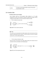
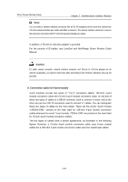
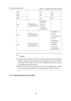
3Com Router Module Guide Chapter 3 Multifunctional Interface Modules Caution: Read the mark identifying a port before you connect a cable to it, making sure it is the correct port. Wrong connection tends to damage interface modules and even the Router; Some protection measures are taken for Router 2 and 4-Port CE1/PRI MIM and modules. Still, you are recommended to install a special lightning arrester at the input end of the cable leading to the outdoors in order to protect the line against lightning strikes more efficiently. I. Connecting interface cable of 1E1/2E1 and modules Step 1: Check the type of cable, and set the DIP switches module correctly; Step 2: Plug the DB-15 connector of the cable into the port on the module; Step 3: Connect the other end of the cable to the network device; 1) When using 75-ohm unbalanced coaxial cable, z Connect its BNC connector to the device to be connected directly, if cable extension is not needed; z Connect its BNC connector to a coaxial connector and the other end of the coaxial connector to the device to be connected through a 75-ohm trunk cable, if cable extension is needed; Caution: Connect the local Tx wire in the cable to the remote Rx wire and the local Rx wire to the remote Tx wire. DB -15 BNC Router BNC Network devices such as DDN Coaxial connector 75-ohm E1 trunk cable 75-ohm non-balanced coaxial cable Figure 3-45 Extending an 75-ohm unbalanced coaxial cable 3-39
-
 1
1 -
2
-
3
-
4
-
5
-
6
-
7
-
8
-
9
-
10
-
11
-
12
-
13
-
14
-
15
-
16
-
17
-
18
-
19
-
20
-
21
-
22
-
23
-
24
-
25
-
26
-
27
-
28
-
29
-
30
-
31
-
32
-
33
-
34
-
35
-
36
-
37
-
38
-
39
-
40
-
41
-
42
-
43
-
44
-
45
-
46
-
47
-
48
-
49
-
50
-
51
-
52
-
53
-
54
-
55
-
56
-
57
-
58
-
59
-
60
-
61
-
62
-
63
-
64
-
65
-
66
-
67
-
68
-
69
-
70
-
71
-
72
-
73
-
74
-
75
-
76
-
77
-
 78
78 -
 79
79 -
 80
80 -
 81
81 -
 82
82 -
 83
83 -
 84
84 -
 85
85 -
 86
86 -
 87
87 -
 88
88 -
89
-
90
-
91
-
92
-
93
-
94
-
95
-
96
-
97
-
98
-
99
-
100
-
101
-
102
-
103
-
104
-
105
-
106
-
107
-
108
-
109
-
110
-
111
-
112
-
113
-
114
-
115
-
116
-
117
-
118
-
119
-
120
-
121
-
122
-
123
-
124
-
125
-
126
-
127
-
128
-
129
-
130
-
131
-
132
-
133
-
134
-
135
-
136
-
137
-
138
-
139
-
140
-
141
-
142
-
143
-
144
-
145
-
146
-
147
-
148
-
149
-
150
-
151
-
152
-
153
-
154
-
155
-
156
-
157
-
158
-
159
-
160
-
161
-
162
-
163
-
164
-
165
-
166
-
167
-
168
-
169
-
170
-
171
 |
 |
