3Com 3C13886 Installation Guide - Page 31
Interface LEDs, DIP switch, Description, impedance, ohm impedance, Table 2-11
 |
UPC - 662705478456
View all 3Com 3C13886 manuals
Add to My Manuals
Save this manual to your list of manuals |
Page 31 highlights
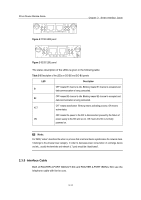
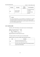
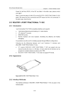
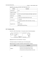
3Com Router Module Guide DIP switch Description Switch for RxShield 8BIT grounding options Chapter 2 Smart Interface Cards 75 -ohm impedance - 120 -ohm impedance OFF: RxShield grounding via capacitor ON: RxShield directly grounding Caution: z When setting internal DIP switch, you are recommended to: turn ON all BITs from 1 to 8 when a 75-ohm cable is connected. Turn OFF all BITs from 1 to 8 when a 120-ohm cable is connected; z The default configuration of internal DIP switch is that all the 8 positions of the BIT switch are ON, that is, the E1 interface impedance is 75-ohm. 2.4.5 Interface LEDs ROUTER 1-PORT FRACTIONAL E1 SIC panel is shown in the following figure: Fractional E1 Figure 2-15 ROUTER 1-PORT FRACTIONAL E1 SIC panel The status description of the LEDs is given in the following table: Table 2-11 Description of the LEDs on ROUTER 1-PORT FRACTIONAL E1 SIC panel LED Description ON means carrier signal has been received. LINK OFF means no carrier signal has been received. OFF means no data is being transmitted or received; blinking means data is ACT being received or/and transmitted. 2-16
-
 1
1 -
2
-
3
-
4
-
5
-
6
-
7
-
8
-
9
-
10
-
11
-
12
-
13
-
14
-
15
-
16
-
17
-
18
-
19
-
20
-
21
-
22
-
23
-
24
-
25
-
 26
26 -
 27
27 -
 28
28 -
 29
29 -
 30
30 -
 31
31 -
 32
32 -
 33
33 -
 34
34 -
 35
35 -
 36
36 -
37
-
38
-
39
-
40
-
41
-
42
-
43
-
44
-
45
-
46
-
47
-
48
-
49
-
50
-
51
-
52
-
53
-
54
-
55
-
56
-
57
-
58
-
59
-
60
-
61
-
62
-
63
-
64
-
65
-
66
-
67
-
68
-
69
-
70
-
71
-
72
-
73
-
74
-
75
-
76
-
77
-
78
-
79
-
80
-
81
-
82
-
83
-
84
-
85
-
86
-
87
-
88
-
89
-
90
-
91
-
92
-
93
-
94
-
95
-
96
-
97
-
98
-
99
-
100
-
101
-
102
-
103
-
104
-
105
-
106
-
107
-
108
-
109
-
110
-
111
-
112
-
113
-
114
-
115
-
116
-
117
-
118
-
119
-
120
-
121
-
122
-
123
-
124
-
125
-
126
-
127
-
128
-
129
-
130
-
131
-
132
-
133
-
134
-
135
-
136
-
137
-
138
-
139
-
140
-
141
-
142
-
143
-
144
-
145
-
146
-
147
-
148
-
149
-
150
-
151
-
152
-
153
-
154
-
155
-
156
-
157
-
158
-
159
-
160
-
161
-
162
-
163
-
164
-
165
-
166
-
167
-
168
-
169
-
170
-
171
 |
 |
