3Com 3C13886 Installation Guide - Page 23
Connecting Interface Cable,
 |
UPC - 662705478456
View all 3Com 3C13886 manuals
Add to My Manuals
Save this manual to your list of manuals |
Page 23 highlights
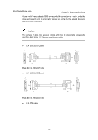
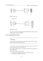
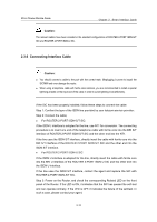
3Com Router Module Guide Chapter 2 Smart Interface Cards Figure 2-7 V.35 DTE cable z V.35 DCE cable Figure 2-8 V.35 DCE cable For the pinouts of synchronous/asynchronous serial interface cable, see Low-End and Mid-Range Series Routers Cable Manual. 2.2.6 Connecting Interface Cable Warning: Do not plug or unplug synchronous/asynchronous serial interface cables when the Router has power. Otherwise, it is likely to damage the equipment and ports. If the SIC has been properly installed, follow these steps to connect the synchronous/asynchronous serial interface cable: Step 1: Insert the DB50 connector of the cable into the DB50 port on the ROUTER 1-PORT SERIAL SIC; Step 2: Connect the other end of the cable to: z CSU/DSU (a type of data transfer device), if the WAN is a DDN line, or z Analog modem, if the WAN is a dial-up line. 2-8
-
 1
1 -
2
-
3
-
4
-
5
-
6
-
7
-
8
-
9
-
10
-
11
-
12
-
13
-
14
-
15
-
16
-
17
-
 18
18 -
 19
19 -
 20
20 -
 21
21 -
 22
22 -
 23
23 -
 24
24 -
 25
25 -
 26
26 -
 27
27 -
 28
28 -
29
-
30
-
31
-
32
-
33
-
34
-
35
-
36
-
37
-
38
-
39
-
40
-
41
-
42
-
43
-
44
-
45
-
46
-
47
-
48
-
49
-
50
-
51
-
52
-
53
-
54
-
55
-
56
-
57
-
58
-
59
-
60
-
61
-
62
-
63
-
64
-
65
-
66
-
67
-
68
-
69
-
70
-
71
-
72
-
73
-
74
-
75
-
76
-
77
-
78
-
79
-
80
-
81
-
82
-
83
-
84
-
85
-
86
-
87
-
88
-
89
-
90
-
91
-
92
-
93
-
94
-
95
-
96
-
97
-
98
-
99
-
100
-
101
-
102
-
103
-
104
-
105
-
106
-
107
-
108
-
109
-
110
-
111
-
112
-
113
-
114
-
115
-
116
-
117
-
118
-
119
-
120
-
121
-
122
-
123
-
124
-
125
-
126
-
127
-
128
-
129
-
130
-
131
-
132
-
133
-
134
-
135
-
136
-
137
-
138
-
139
-
140
-
141
-
142
-
143
-
144
-
145
-
146
-
147
-
148
-
149
-
150
-
151
-
152
-
153
-
154
-
155
-
156
-
157
-
158
-
159
-
160
-
161
-
162
-
163
-
164
-
165
-
166
-
167
-
168
-
169
-
170
-
171
 |
 |
