3Com 3C13886 Installation Guide - Page 149
Interface Optical Fiber, Table 4-24, Description
 |
UPC - 662705478456
View all 3Com 3C13886 manuals
Add to My Manuals
Save this manual to your list of manuals |
Page 149 highlights
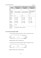
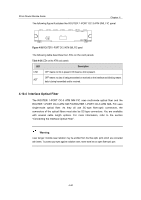
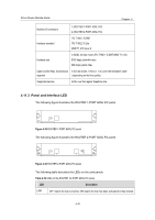
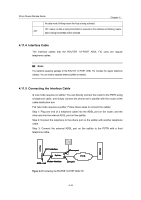
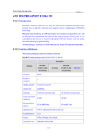
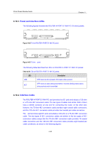
3Com Router Module Guide Chapter 4 The following figure illustrates the ROUTER 1-PORT OC-3 ATM SML FIC panel. Figure 4-38 ROUTER 1-PORT OC-3 ATM SML FIC panel The following table describes the LEDs on the card panels. Table 4-24 LEDs on the ATM card panels LED Description LINK OFF means no link is present; ON means a link is present. OFF means no data is being transmitted or received on the interface and blinking means ACT data is being transmitted and/or received. 4.10.4 Interface Optical Fiber The ROUTER 1-PORT OC-3 ATM MM FIC uses multi-mode optical fiber and the ROUTER 1-PORT OC-3 ATM SM FIC/ROUTER 1-PORT OC-3 ATM SML FIC uses single-mode optical fiber. As they all use SC-type fiber-optic connectors, the connectors of the optical fibers must also be SC-type connectors. You are available with several cable length options. For more information, refer to the section "Connecting the Interface Optical Fiber". Warning: Laser danger: Invisible laser radiation may be emitted from the fiber-optic ports which are connected with lasers. To protect your eyes against radiation harm, never stare into an open fiber-optic port. 4-40
-
 1
1 -
2
-
3
-
4
-
5
-
6
-
7
-
8
-
9
-
10
-
11
-
12
-
13
-
14
-
15
-
16
-
17
-
18
-
19
-
20
-
21
-
22
-
23
-
24
-
25
-
26
-
27
-
28
-
29
-
30
-
31
-
32
-
33
-
34
-
35
-
36
-
37
-
38
-
39
-
40
-
41
-
42
-
43
-
44
-
45
-
46
-
47
-
48
-
49
-
50
-
51
-
52
-
53
-
54
-
55
-
56
-
57
-
58
-
59
-
60
-
61
-
62
-
63
-
64
-
65
-
66
-
67
-
68
-
69
-
70
-
71
-
72
-
73
-
74
-
75
-
76
-
77
-
78
-
79
-
80
-
81
-
82
-
83
-
84
-
85
-
86
-
87
-
88
-
89
-
90
-
91
-
92
-
93
-
94
-
95
-
96
-
97
-
98
-
99
-
100
-
101
-
102
-
103
-
104
-
105
-
106
-
107
-
108
-
109
-
110
-
111
-
112
-
113
-
114
-
115
-
116
-
117
-
118
-
119
-
120
-
121
-
122
-
123
-
124
-
125
-
126
-
127
-
128
-
129
-
130
-
131
-
132
-
133
-
134
-
135
-
136
-
137
-
138
-
139
-
140
-
141
-
142
-
143
-
 144
144 -
 145
145 -
 146
146 -
 147
147 -
 148
148 -
 149
149 -
 150
150 -
 151
151 -
 152
152 -
 153
153 -
 154
154 -
155
-
156
-
157
-
158
-
159
-
160
-
161
-
162
-
163
-
164
-
165
-
166
-
167
-
168
-
169
-
170
-
171
 |
 |
