3Com 3C13886 Installation Guide - Page 17
Interface Cable, Connecting the Interface Cable,
 |
UPC - 662705478456
View all 3Com 3C13886 manuals
Add to My Manuals
Save this manual to your list of manuals |
Page 17 highlights
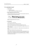
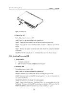
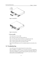
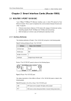
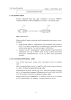
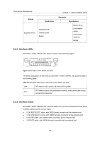
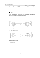
3Com Router Module Guide being received or/and transmitted. Chapter 2 Smart Interface Cards 2.1.2 Interface Cable Normally, category-5 twisted pair cable is adopted to connect the 10BASE-T /100BASE-TX Ethernet interface to the Ethernet, as shown in the following figure: Figure 2-2 Ethernet cable Ethernet cables fall into two categories: straight-through cables and crossover cables, specifically, z Straight-through cable: the wire sequences of the twisted pair cable crimped in the RJ-45 connectors at both ends are completely the same. It is used to connect terminal devices (such as PCs, routers) to Hubs or LAN Switches. z Crossover cable: The wire sequences of twisted pair cable crimped in the RJ-45 connectors at both ends are different. It can be used to connect two terminal devices (such as PCs and Routers). You can such kind of cables by yourself if necessary. 2.1.3 Connecting the Interface Cable If the SIC has been properly installed, follow these steps to connect the interface cable: Step 1: Connect the Ethernet port of SIC to a PC or router using a crossover cable and to a Hub or LAN Switch using a straight-through cable; Step 2: Power on the Router and check the SLOT1 LED on its front panel: ON means that the SIC is operating normally and OFF means that the Power-On Self-Test (POST) of the SIC has failed. In the latter case, please contact your agent. Step 3: Check the status of LINK LED on the panel: ON means the link is connected and OFF means the link is not connected. In the latter case, check the line. 2-2
-
 1
1 -
2
-
3
-
4
-
5
-
6
-
7
-
8
-
9
-
10
-
11
-
 12
12 -
 13
13 -
 14
14 -
 15
15 -
 16
16 -
 17
17 -
 18
18 -
 19
19 -
 20
20 -
 21
21 -
 22
22 -
23
-
24
-
25
-
26
-
27
-
28
-
29
-
30
-
31
-
32
-
33
-
34
-
35
-
36
-
37
-
38
-
39
-
40
-
41
-
42
-
43
-
44
-
45
-
46
-
47
-
48
-
49
-
50
-
51
-
52
-
53
-
54
-
55
-
56
-
57
-
58
-
59
-
60
-
61
-
62
-
63
-
64
-
65
-
66
-
67
-
68
-
69
-
70
-
71
-
72
-
73
-
74
-
75
-
76
-
77
-
78
-
79
-
80
-
81
-
82
-
83
-
84
-
85
-
86
-
87
-
88
-
89
-
90
-
91
-
92
-
93
-
94
-
95
-
96
-
97
-
98
-
99
-
100
-
101
-
102
-
103
-
104
-
105
-
106
-
107
-
108
-
109
-
110
-
111
-
112
-
113
-
114
-
115
-
116
-
117
-
118
-
119
-
120
-
121
-
122
-
123
-
124
-
125
-
126
-
127
-
128
-
129
-
130
-
131
-
132
-
133
-
134
-
135
-
136
-
137
-
138
-
139
-
140
-
141
-
142
-
143
-
144
-
145
-
146
-
147
-
148
-
149
-
150
-
151
-
152
-
153
-
154
-
155
-
156
-
157
-
158
-
159
-
160
-
161
-
162
-
163
-
164
-
165
-
166
-
167
-
168
-
169
-
170
-
171
 |
 |
