3Com 3C13886 Installation Guide - Page 69
Router 2 And 4-port Enhanced Serial Mim
 |
UPC - 662705478456
View all 3Com 3C13886 manuals
Add to My Manuals
Save this manual to your list of manuals |
Page 69 highlights
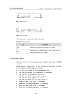
3Com Router Module Guide Chapter 3 Multifunctional Interface Modules Caution: Before connecting an SA module, confirm the model of the equipment to be connected to the SA module (that is, sync/async mode, DTE/DCE mode, and so on), signaling criterion required by the access equipment, baud rate, and timing clock. I. Connecting interface cable of Router 4-Port Serial MIM Step 1: Plug the DB-100 connector of a Router 4-Port Serial MIM conversion cable to the appropriate DB-100 port on the Router 4-Port Serial MIM module; Step 2: Select a correct sync/async serial interface cable. Connect one end of the cable to the DB50 connector of the Router 4-Port Serial MIM conversion cable and the other end to: z Port of CSU/DSU, if the WAN is a DDN line; z Serial port of analog modem, if the WAN is a dial-up line; Step 3: Power on the Router, and check the LEDs of the corresponding slot on the front panel: ON means that the MIM is operating normally and OFF means that the POST of the MIM has failed. In the latter case, please contact your agent. Step 4: Check the behavior of the LINK LED on the Router 4-Port Serial MIM panel. It is OFF when the line is faulty and signal is out of synchronization. Caution: You should connect a cable to the port with the correct mark. Misplugging is prone to impair the SIC/MIM and even damage the router. 3.7 ROUTER 2 AND 4-PORT ENHANCED SERIAL MIM 3.7.1 Introduction ROUTER 2 AND 4-PORT ENHANCED SERIAL MIM, 2-/4-port enhanced high-speed sync/async serial interface card, transmits, receives, and processes data on the synchronous/asynchronous serial interface. They support both synchronous and asynchronous modes. In the former case, they support the DTE/DCE mode. I. DTE and DCE An FIC-SA card is usually connected to an external modem for dialing purpose, where an appropriate baud rate setting is required. 3-25
-
 1
1 -
2
-
3
-
4
-
5
-
6
-
7
-
8
-
9
-
10
-
11
-
12
-
13
-
14
-
15
-
16
-
17
-
18
-
19
-
20
-
21
-
22
-
23
-
24
-
25
-
26
-
27
-
28
-
29
-
30
-
31
-
32
-
33
-
34
-
35
-
36
-
37
-
38
-
39
-
40
-
41
-
42
-
43
-
44
-
45
-
46
-
47
-
48
-
49
-
50
-
51
-
52
-
53
-
54
-
55
-
56
-
57
-
58
-
59
-
60
-
61
-
62
-
63
-
 64
64 -
 65
65 -
 66
66 -
 67
67 -
 68
68 -
 69
69 -
 70
70 -
 71
71 -
 72
72 -
 73
73 -
 74
74 -
75
-
76
-
77
-
78
-
79
-
80
-
81
-
82
-
83
-
84
-
85
-
86
-
87
-
88
-
89
-
90
-
91
-
92
-
93
-
94
-
95
-
96
-
97
-
98
-
99
-
100
-
101
-
102
-
103
-
104
-
105
-
106
-
107
-
108
-
109
-
110
-
111
-
112
-
113
-
114
-
115
-
116
-
117
-
118
-
119
-
120
-
121
-
122
-
123
-
124
-
125
-
126
-
127
-
128
-
129
-
130
-
131
-
132
-
133
-
134
-
135
-
136
-
137
-
138
-
139
-
140
-
141
-
142
-
143
-
144
-
145
-
146
-
147
-
148
-
149
-
150
-
151
-
152
-
153
-
154
-
155
-
156
-
157
-
158
-
159
-
160
-
161
-
162
-
163
-
164
-
165
-
166
-
167
-
168
-
169
-
170
-
171
 |
 |
