3Com 3C13886 Installation Guide - Page 50
Table 3-3, Router side, RJ-45 Pin, RJ-45 interface signal, Signal at switch side Bell V 4-wire
 |
UPC - 662705478456
View all 3Com 3C13886 manuals
Add to My Manuals
Save this manual to your list of manuals |
Page 50 highlights
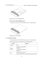
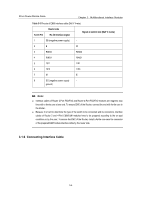
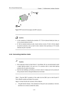
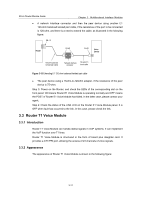
3Com Router Module Guide Chapter 3 Multifunctional Interface Modules Table 3-3 Pinouts of E&M interface cable (Bell V 4-wire) RJ-45 Pin Router side RJ-45 interface signal Signal at switch side (Bell V 4-wire) 1 SB (negative power supply) - 2 E M 3 RING0 RING0 4 RING1 RING1 5 TIP1 TIP1 6 TIP0 TIP0 7 M E 8 SG (negative power supply - ground) Note: z Interface cables of Router 2-Port FXS/FXO and Router 4-Port FXS/FXO modules are magnetic loop lines with a ferrite core at one end. To ensure EMC of the Router, connect the end with ferrite core to the Router. z Because it is hard to determine the type of the switch to be connected and its connectors, interface cables of Router 2 and 4-Port E&M/E&M modules have to be prepared according to the on-spot conditions or by the user. To ensure the EMC of the Router, install a ferrite core near the connector of the prepared E&M module interface cable by the router side. 3.1.6 Connecting Interface Cable 3-6
-
 1
1 -
2
-
3
-
4
-
5
-
6
-
7
-
8
-
9
-
10
-
11
-
12
-
13
-
14
-
15
-
16
-
17
-
18
-
19
-
20
-
21
-
22
-
23
-
24
-
25
-
26
-
27
-
28
-
29
-
30
-
31
-
32
-
33
-
34
-
35
-
36
-
37
-
38
-
39
-
40
-
41
-
42
-
43
-
44
-
 45
45 -
 46
46 -
 47
47 -
 48
48 -
 49
49 -
 50
50 -
 51
51 -
 52
52 -
 53
53 -
 54
54 -
 55
55 -
56
-
57
-
58
-
59
-
60
-
61
-
62
-
63
-
64
-
65
-
66
-
67
-
68
-
69
-
70
-
71
-
72
-
73
-
74
-
75
-
76
-
77
-
78
-
79
-
80
-
81
-
82
-
83
-
84
-
85
-
86
-
87
-
88
-
89
-
90
-
91
-
92
-
93
-
94
-
95
-
96
-
97
-
98
-
99
-
100
-
101
-
102
-
103
-
104
-
105
-
106
-
107
-
108
-
109
-
110
-
111
-
112
-
113
-
114
-
115
-
116
-
117
-
118
-
119
-
120
-
121
-
122
-
123
-
124
-
125
-
126
-
127
-
128
-
129
-
130
-
131
-
132
-
133
-
134
-
135
-
136
-
137
-
138
-
139
-
140
-
141
-
142
-
143
-
144
-
145
-
146
-
147
-
148
-
149
-
150
-
151
-
152
-
153
-
154
-
155
-
156
-
157
-
158
-
159
-
160
-
161
-
162
-
163
-
164
-
165
-
166
-
167
-
168
-
169
-
170
-
171
 |
 |
